Question

Seeking Technical Guidance: Entrance Slit Size in Spectrometer


I am writing to seek clarification on a technical matter related to the article How to build a spectrometer - theory.

Thanks to your guidance, I was able to successfully reproduce the spectrometer.

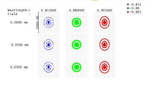
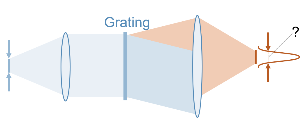
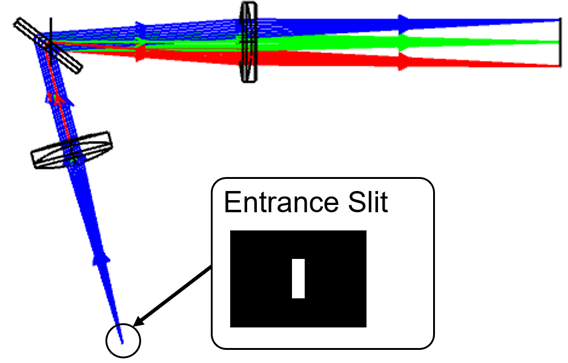
However, I now have a question regarding the consideration of the entrance slit size and its impact on the resulting image or spectral bandwidth.


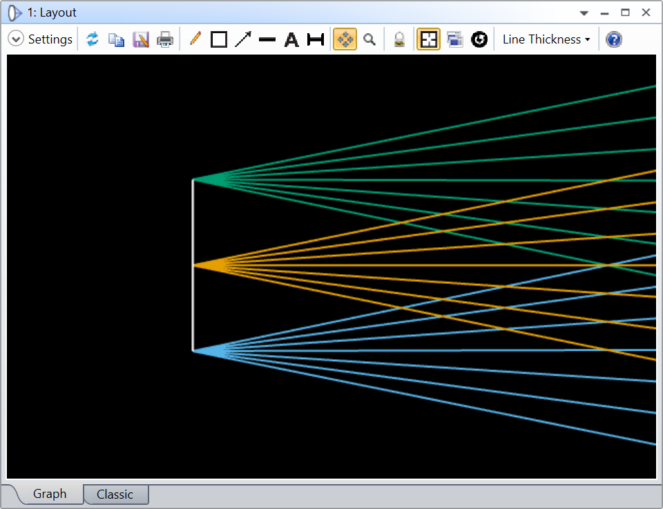
Specifically, I would like to simulate how different entrance slit sizes, such as 10µm or 100µm, affect the performance of the spectrometer.

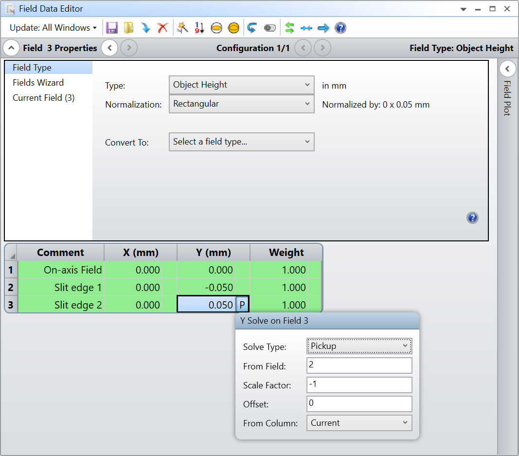
Despite my attempts to manipulate the aperture settings, I have been unable to create a slit in the simulation.

I kindly request your guidance on how to properly take the entrance slit size into consideration during the spectrometer simulation.

Could you please provide me with detailed instructions or suggestions on how to achieve this?


5 replies

Userlevel 7
Badge +2

@FumiyaK


You could define additional fields in the system to create such an entrance slit. If you consider the one-dimensional case along the small dimension of the slit, you can have a field at the center of the slit and two other fields on either side at a distance of half the slit width. For that, I’d use the Field Type: Object Height with a Normalization: rectangular. For a slit of 100um, you can have a field at 50um, and another one at -50um (consider using a pick-up such that you only need to change one value, as shown below).

Fields definition. One field propagates on-axis, and the other two simulate the light at the edges of the slit. I’m using a pickup on the second edge-field such that all one has to do to change the slit width is adjust the Y (mm) of Field 2.
Zoom on the first surface of the system showing how the fields are launched at a distance of 50um between one another. The color coding is now by field and not wavelength anymore.

Does that make sense?

Take care,


David

@David.Nguyen 

Thank you very much for your kind reply.

The function is helpful to examine how the light from the edge of the slit creates focus. However, I am interested in determining the size of the spot based on the size of the slit, as shown below.
I would like to explore the relationship between the size of the slit and the spectral resolution.


Best Regards,

Fumiya

Userlevel 7
Badge +2

@FumiyaK 


Indeed, the spectrometer images the slit onto the detector. Therefore, by imaging the field at the edge of the slit, you know how where the edge of the slit will be on the detector, which gives you the spectral resolution. You could also define more fields and give them intensities that correspond to your light profile in the entrance slit such that you get a more accurate picture of the spectral resolution, but the edge fields will give you a first approximation assuming the light is homogeneous in the entrance slit.

I hope I understood your question correctly.

Take care,


David

Userlevel 2
Badge

or how about calculating the width in non-sequential mode?


Badge

I’m trying to do something similar. Found the guidance here useful: Spot Size VS Spectrometer Slit Width | Zemax Community

So far I’ve stuck with Image Simulation but am getting differences that I don’t yet understand between using a filled square input IMA file and placing a rectangular aperture after the object, and generating an IMA representation of the slit (like this: How to simulate a slit width for Geometric Image Analysis? | Zemax Community)

Reply