Solved

Saving detector data as source file results with wrong output

  • 6 December 2022
  • 2 replies
  • 114 views

Userlevel 2

Hello,


I’m trying to merge multiple sources into a single source by raytracing all the sources onto a detector and save its data as a source file.

I encounter few problems when doing so:

  1. The output rays doesn’t match the expectation, in the image below you can see the blue and cyan rays are the rays I’m trying to copy,  and the khaki rays are the source file that was created. the differences are:
    • The beam output starts at some distance Z away from the detector
    • The diameter and angular distribution looks different from the input rays
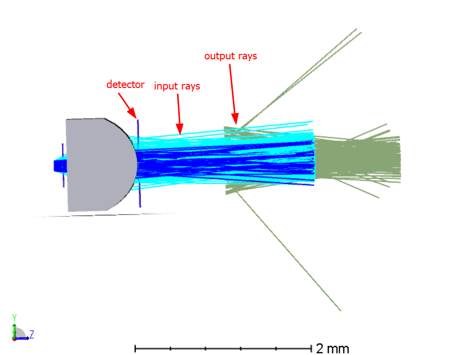
      Side view of the input rays and output rays


  2. The energy distribution doesn’t match, such that its giving more energy to the first defined sources in the NSCE, see below
    Source file raytraced with 1.8E4 analysis rays


I’m adding my files below and would appreciate help.


Thanks,

Oran

icon

Best answer by Oran 7 December 2022, 10:04

View original

2 replies

Userlevel 6
Badge +4

Hi Oran,

I suggest correcting the positioning problem first.

The issue is that the coordinates of the rays in the .dat file are referenced to the global coordinate system of the design file in which they were originally saved. So if the detector on which ray strikes were saved was not at the origin (0,0,0) of the first file, then they carry an offset. For example, if the original detector was on axis at (0,0,z0), then each of the saved rays will have coordinates of some (x,y,z0).

When you place the Source File in the new design, say at some on axis location (0,0,z1), then the the rays will each originate from some location (x,y,z0+z1).

If you want the rays in the design that uses the Source File to originate from the location at which you place the Source File (I usually do), then the thing to do is to modify the design from which the .dat file is created so as to place the detector on which rays are saved at (0,0,0) of the design coordinate system. This is easily done with the Modify Reference Object tool in the menu bar of the Non-sequential Component Editor.

There is another post on this topic here.

In the future, I suggest posting your design for upload as a ZAR file. That will include the dat file and also the analysis windows so we an see the design just as you do.  :-)


Userlevel 2

Hi Oran,

I suggest correcting the positioning problem first.

The issue is that the coordinates of the rays in the .dat file are referenced to the global coordinate system of the design file in which they were originally saved. So if the detector on which ray strikes were saved was not at the origin (0,0,0) of the first file, then they carry an offset. For example, if the original detector was on axis at (0,0,z0), then each of the saved rays will have coordinates of some (x,y,z0).

When you place the Source File in the new design, say at some on axis location (0,0,z1), then the the rays will each originate from some location (x,y,z0+z1).

If you want the rays in the design that uses the Source File to originate from the location at which you place the Source File (I usually do), then the thing to do is to modify the design from which the .dat file is created so as to place the detector on which rays are saved at (0,0,0) of the design coordinate system. This is easily done with the Modify Reference Object tool in the menu bar of the Non-sequential Component Editor.

There is another post on this topic here.


Thank you for your advice David, it solved to position as you said.


It seems like the way to avoid the ray distribution issues was to read the number of hit rays on the detector and to apply the same number to the new source.

Reply