Question

Reimaged axicon setup

  • 11 September 2021
  • 6 replies
  • 1134 views

Badge


Hi all,

I hope you are all still doing well.

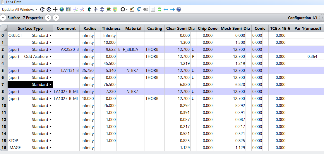
I have been trying to plot the peak irradiance of a reimaged Bessel-Gauss beam produced using a 20 degree axicon (AX2520-B, Thorlabs). The reimaging telescope consists of a 50 mm plano-convex lens (LA1131-B, Thorlabs) and a 35 mm plano-convex lens (LA1027-B, Thorlabs). The first lens (the 50 mm one) is placed 45.5 mm away from the conical tip, as this is its front focal length (approximately 42 mm) away from the centre of the Bessel-zone produced by the axicon.

Lens Data window
Layout of reimaged axicon setup, surface 7 highlighted

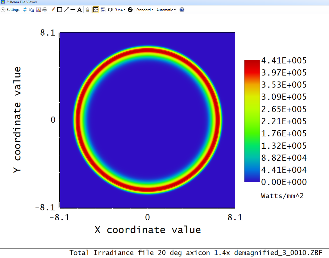
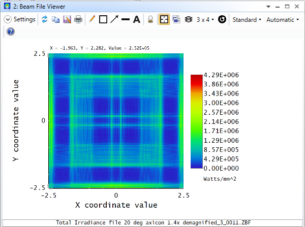
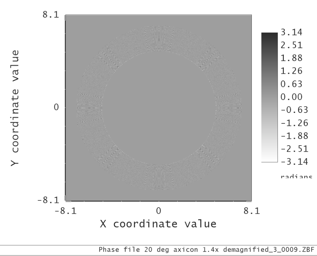
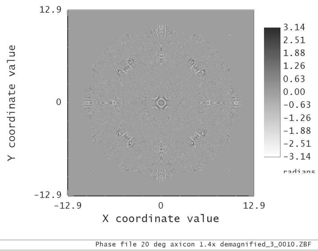
I have been able to obtain sampling that provides an annular ring at the back surface (surface 7, highlighted in above image) of the 50 mm lens (as would be expected), but upon reaching the planar surface of the 35 mm lens the beam shape appears significantly distorted. I have opted for 20 x 20 mm X and Y widths, with a sampling rate of 8192 x 8192.

Surface 7 irradiance false colour plot - annular ring

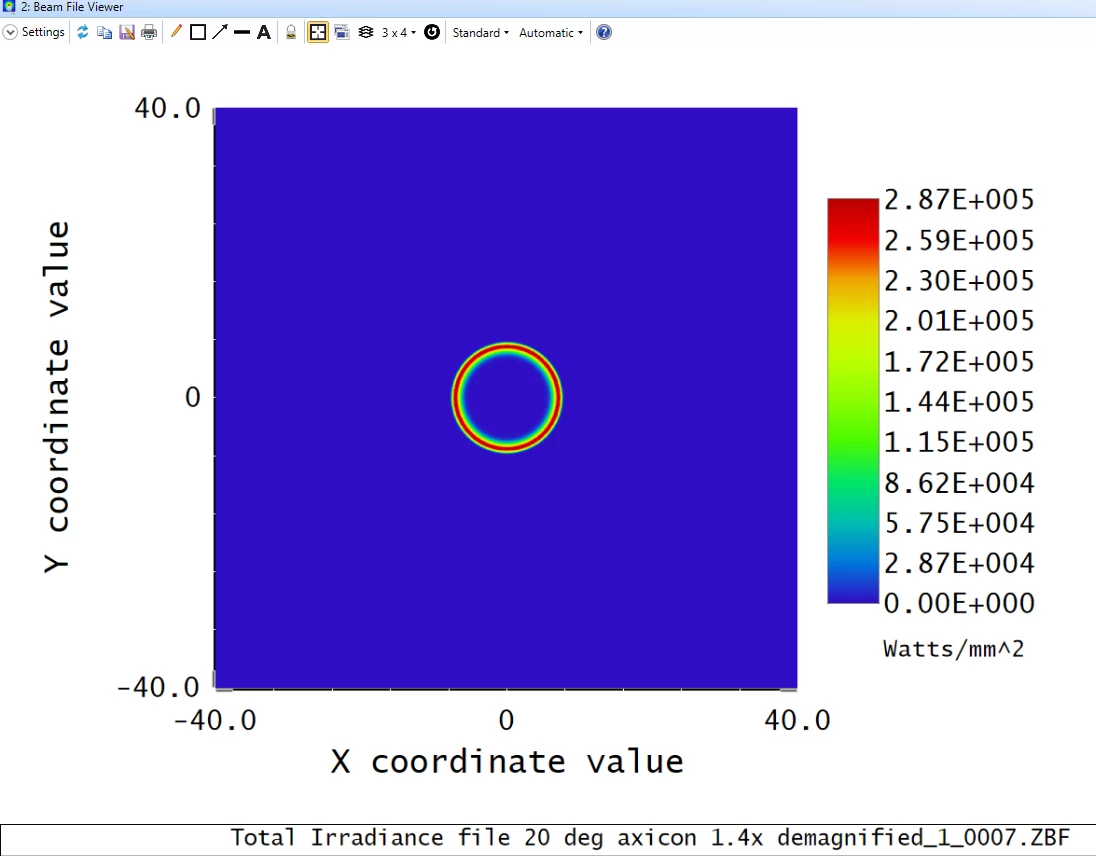
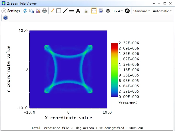
                            Surface 8 irradiance false colour plot - distorted (not an annular ring as expected)

POP sampling settings

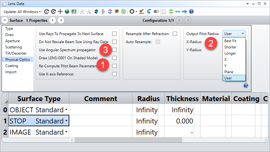
The output pilot radius is set to “Plane” at surface 3 (the conical tip surface of the axicon), and I have played around with resampling the beam at surface 7 (the planar surface of the 50 mm lens) to adequately resolve the beam at surface 8 (the planar surface of the 35 mm lens), but to no avail.

I see the beam reaches a diameter of around 20 mm at surface 8, thus I attempted initial X- and Y- widths of 30 mm (to provide an adequate guard band of at least 3x further along the propagation, as per the POP help articles available in the Knowledgebase), but upon going to these I lose the annular ring beam shape at surfaces 5, 6 and 7.

While I have encountered similar issues before arising from an inadequate guard band, no such error message arises in the “Prop report” tab of the Physical Optics Propagation window, thus I am not sure what I am currently missing? I would like to resolve the peak irradiance across the reimaged Bessel zone around surfaces 11-14. I have attached the .ZMX file for reference.

Thank you all for your time. 


6 replies

Badge

Hi all, I believe I have found a workaround to this issue by simply selecting the “Use Rays To Propagate To Next Surface” option, but I am now having difficulty visualising the Bessel profile at surface 11 onwards.

Previously I have used the “Resample After Refraction” option when going from an input Gaussian beam to the significantly smaller central core of the Bessel profile produced by an axicon. However, in this instance I observe odd interference patterns upon trying to do this (in this example resampling to a 5 x 5 mm frame width with 8192x8192 sampling at surface 11).

Annular ring beam profile at surface 10
Disrupted beam profile at surface 11.

Thanks again for your time.

Userlevel 7
Badge +3

What are you using as a phase reference when the beam is reformed after being propagated as rays?

Best to look at the phase rather than the irradiance as you get this setup. The phase is what really drives the calculation, so find the first surface at which it is undersampled, and either upsample it or use a better reference.

- Mark

Badge

Hi Mark,

Thanks for taking the time to help out again!

Regarding the phase reference (and having read your article “How to use POP with lenslet arrays”) I have not created a new one since the input surface. I assume this means I need to “Re-Compute Pilot Beam Parameters” at surface 8 (the planar surface of the 35 mm plano-convex lens, to which the “Use Rays to Propagate to Next Surface” option was used from surface 7)? Otherwise I am unsure how to alter the reference?

Regarding the phase sampling, I believe the beam appears adequately sampled until surface 9 (the one prior to where beam distortion/deviation from the expected shape is observed)? 

Phase at axicon conical surface (surface 3), 4x zoomed
Phase at surface 5, 50 mm lens planar surface
Phase at surface 9, convex surface of 35 mm focusing/imaging lens

Additionally, I have tried setting the “Output Pilot Radius” to “Plane” at surface 9 (the convex/curved surface of the 35 mm lens), but distortion from the expected Bessel beam distribution is still observed afterwards (surface 10 onwards).

Phase at surface 10, 26 mm after surface 9

Thanks again for your time and any help you can provide.

Userlevel 7
Badge +3

Hmm...tricky

The phase of the POP beam is modulo 2pi after the pilot beam radius is subtracted. You can recompute the pilot on any surface(1), and in most systems it is not required. The ‘Best Fit’ Output Pilot Radius is the best-git Gaussian to the beam data. Since your beam is a Bessel, the best-fit Gaussian is probably not much use.

The Nyquist sampling s to to have at least two pixels per wave, which is why when you have many waves of phase you have to turn the sampling way up.

Shorter and Longer just use the shorter and longer of the X or Y slices, and X or Y will choose just that orientation. None of these seem like preferable options. So I think Plane is the only reference that makes sense for your case. You could possible contract with Zemax to provide a Bessel function reference for this case. AFAIK, this would need a Zemax programmer and can’t be done through ZOS-API or any other interface.

One other thing occurs to me. The pilot beam radius is also used to select the propagation method. Since the point of a Bessel beam is to not change as it is propagated, it may be best to not use the pilot beam for that task either and to “use Angular Spectrum” (item (3) above) instead. With the plane reference and Use ASP selected you really only have the sampling to play with...you are driving the POP algorithm 100% manually and there’s only sampling (and hence calculation time & memory) to compute the correct result.

Hope that helps. I’ll be happy to take a look at your file and see if I can suggest anything more. Post it here or send it to markgnicholson (at) gmail.com and I’ll take a look.


  • Mark


Badge

Hi Mark,

Thanks for the suggestions.

I have attached the files as requested.

Regarding the “use Angular Spectrum” option, which surface would you suggest using this at? I at first thought it would be good to use at surface 9 (i.e. prior to the reimaged Bessel zone) but I note that it says it is only suitable for when the beam does not change rapidly in size.

Thank you once again for your time.

Kind regards,

Donald

Badge

Hi all,

Just as a quick update, I have also tried modelling the setup using the non-sequential mode by implementing a detector surface (see attached files), but unfortunately this seems unable to account for the phase/interference that leads to the formation of the Bessel beam profile at both the unmodified and reimaged Bessel zones.

Any further help/suggestions would be greatly appreciated.

Thank you again for your time.

Kind regards,

Donald 

Reply