Question

rays intersect problem

  • 11 July 2023
  • 6 replies
  • 98 views

Userlevel 1
Badge

Hi everyone,

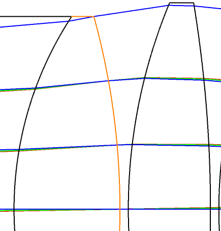
    I’ve been working on the microscope objective design and stumbled cross a design in Zemax design templates. Rays don’t intersect exactly on the stop surface(10th) even with the “paraxial”ray aiming on. Why is that? I expected the rays would intersect exactly on the stop surface.


6 replies

Userlevel 7
Badge +2

Hi @steven.Ou,


Is this design in the sample files? Which one is it?

Have you tried Real Ray Aiming as well? There’s also been a relatively recent release of “enhanced” ray aiming that might be useful for you:

https://support.zemax.com/hc/en-us/articles/4415991777299-Introduction-to-Enhanced-Ray-Aiming-and-Ray-Aiming-Wizard

Take care,


David


Userlevel 6
Badge +2

Hi Steven, 

If you look at the Field Data Editor, you can see that there are Vignetting Factors for Field 2 and Field 3.  Vignetting Factors intentionally make the rays for different fields to not overlap at the Stop location.  If you remove the VDY, VCX, & VCY you will see the rays intersect at the Stop location:

@David.Nguyen The file is the first microscope after the Boge design in the Libraries > Design Templates.  This used to actually have a name in Zebase but now that it’s in Design Templates, the file is loaded as a temporary file so you can’t easily find it except going through the Design Templates.

Userlevel 7
Badge +2

Thank you @MichaelH! Can you comment on why one would want to intentionally not overlap the fields at the Stop? Thanks a lot :)

Userlevel 6
Badge +2

Hey David,

Rather than thinking of “overlapping fields at the Stop”, remember that Vignetting Factors are a tool that should only be used early on in the design during optimization and final analysis should remove Vignetting Factors and ensure all surfaces have a hard aperture (this is what the Design Lockdown does).  A designer would use the Vignetting Factors early in the design if they know there will be a limiting aperture for off-axis fields because of size or geometry constraints.

Vignetting Factors is an approximation for early analysis to ensure that all 4 marginal rays make it through the system since a few Optimization operands rely on the marginal rays, but this approximation uses an ellipse rather than the actual Cat’s Eye you get for vignetted off-axis fields.  To get the actual analysis of a final design, the full beam footprint should be used for each field.

Userlevel 7
Badge +2

Brilliant @MichaelH, thank you!

Userlevel 1
Badge

HI @David.Nguyen  @MichaelH  ,thank you, guys.


Reply