Question

Ray artefact at 45° object angle in my lens design


Dear All,


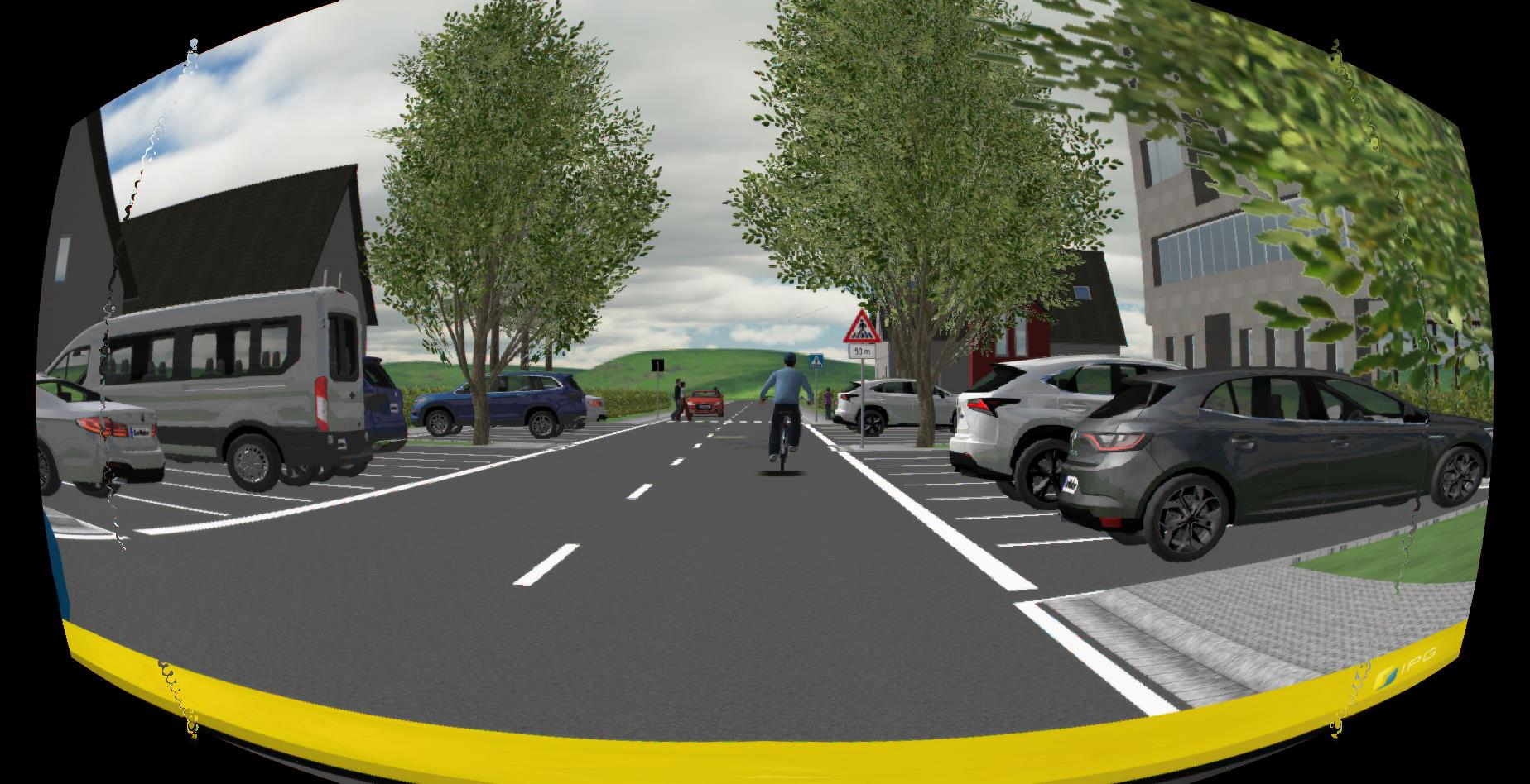
I see an artefact in rays being projected from 45° to the first lens surface.

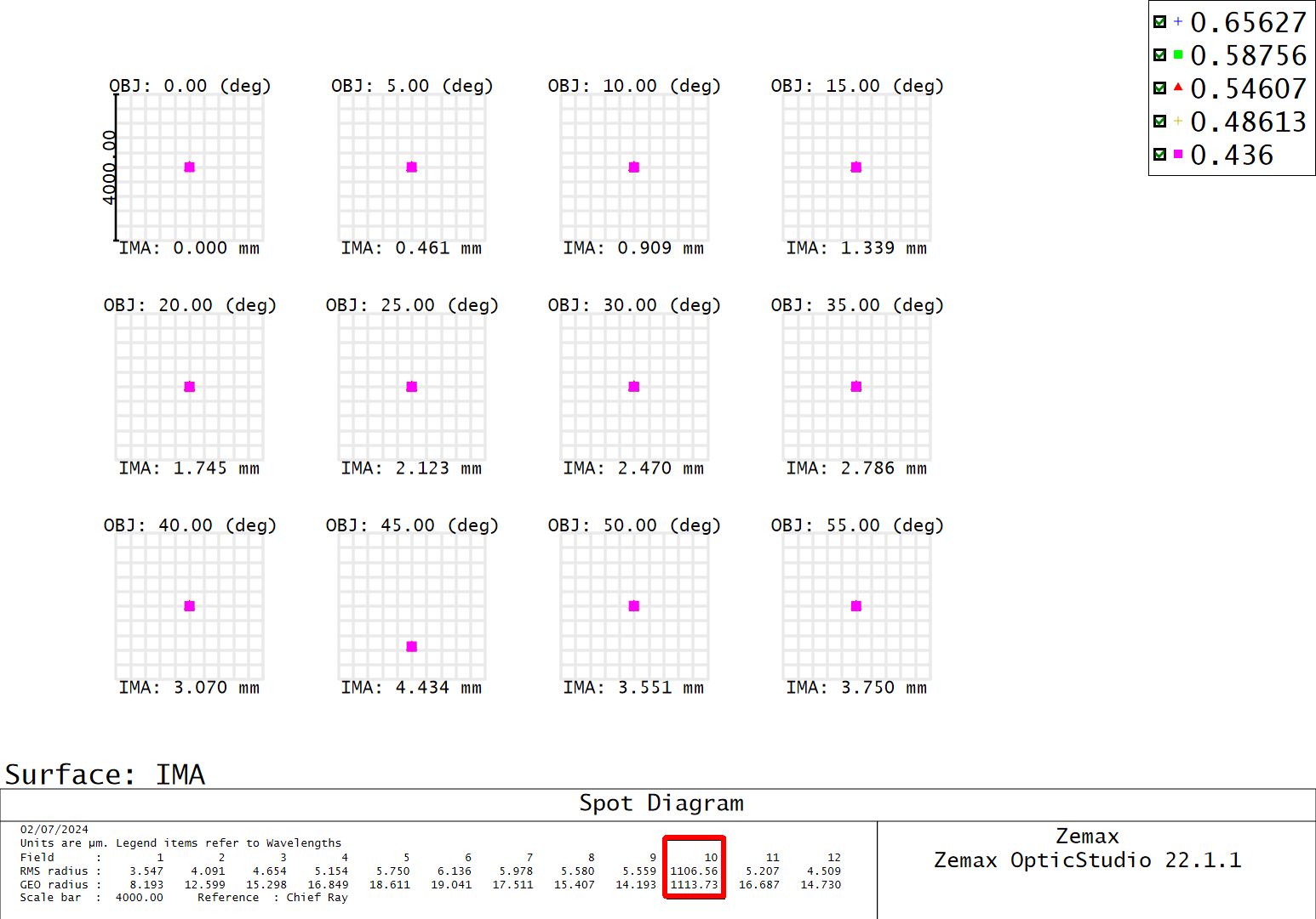
One of the rays does not hit the lens surface as shown here:
 

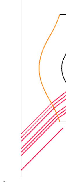
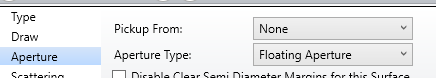
The first surface is a dummy surface because object distance is infinity.

The spot diagram show a radius of about 1200 µm whereas the spot radius for other object angles is between 4 and 9 µm. Surprisingly 40° and 50° object angle rays do not have same behaviour. 


Is there a way to rectify this or maybe ways to find sources of this artefact?


Any suggestions are welcome.


Regards,

Amit


PS: For confidentiality i could not add an image of the entire cross section of the objective design.

14 replies

Userlevel 4
Badge

Assuming this is a sequential view, have you checked “delete vignetted” option in your view settings ?


Hi Ray,


if i  have “delete vignetted” selected it solves the issue in the ray propagation but does not solve the spot diagram issue:


Userlevel 4
Badge

Hi Amit,


Perhaps a floating aperture on the surface(s) where the ray should be cut could help.


Hi Ray,


thank you for your response. I tried floating apertures individually on most of the surfaces. It does not work.

Userlevel 3
Badge

Have you fixed the front lens Diameter? OR specified s user defined CA?

 Hello Chandan,

Have you fixed the front lens Diameter? OR specified s user defined CA?

yes the first surface has a user defined circular aperture.

Could you please elaborate how that has an impact?


Amit

Userlevel 6
Badge +4

Hi Amit,

I suggest a few things you might look at:

Turn Real Ray Aiming on.

For aperture in the System Explorer, check the settings:

  For Float by Stop Size, make sure the stop is where it should be. Try small values of semidiameter     on the stop surface.

  For Image Space F/#, Check the value. Try large values for a slower system.

  For Entrance Pupil Diameter, try smaller values.


Userlevel 3
Badge

Hi Amit,

If you have restricted the diameter of the lens, it will now allow the lens to adjust the diameter as per your system requirements and therefore with fixed diameter you may not be able to launch the full beam width leading to vignette. To avoid the same it is suggested that fix the lens diameter one the design is complete or control the lens diameters using merit function. Once the optimization is done you can fix the lens diameter.

If lens diameter is fixed and you can not increase it further try the suggestion from @David to adjust your beam diameter.

Thanks.

Userlevel 6
Badge +4

Hi Amit,

This article might relate to the issue: How to Use Ray Aiming

Hi David,

I turned Real Ray Aiming on and selected “Use Enhanced Ray Aiming”.

This solved the issue of spot size at 45° FOV.  All the spots in the spot diagram look reasonable now.

What I see in the Layout diagram is that the rays for angle 45! and beyopnd do not fill the STOP anymore.

Rays from all angles before 45° fill the aperture. 


Also i see an artefact (warped curve close to the edges of the image below) in image simulations which leads me to believe that the issue is not fully resolved and there are more steps to get an artefact free solution to this problem.


However your answer about ray aiming helped mitigate a major part of the problem. Thank you very much for that.


Amit

Userlevel 6
Badge +4

What aperture type have you set in the System Explorer?


What aperture type have you set in the System Explorer?

Image space F/# (1.6)


Amit

Userlevel 6
Badge +4

Then, in my experience, if the stop surface is positioned correctly, and if its semidiameter is set to automatic, it should be filled. If not, I can’t think of the cause. But there are people on this forum with far more experience, like @Mark.Nicholson. Perhaps they might help.

Userlevel 7
Badge +3

That’s very kind, but I’m blind without a file to open and see what’s happening.

Go to Setup...Diagnostics and run the System Check, and let me know what it reports.

  • Mark

Reply