Question

Projected solid angle for circular aperture

  • January 6, 2026
  • 3 replies
  • 45 views

mocquin
Ultraviolet

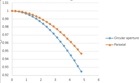
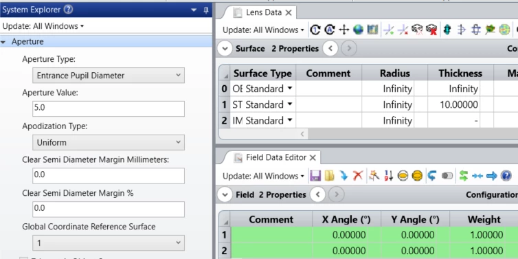
Let’s say my optical setup only has a circular aperture of radius R, with a blackbody surface that overfills this aperture, and image surface at distance h from aperture.

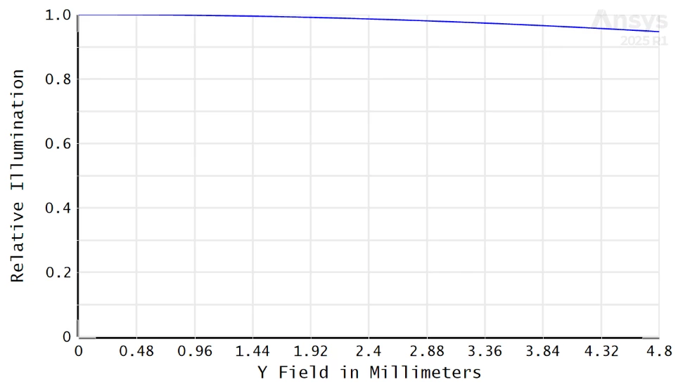
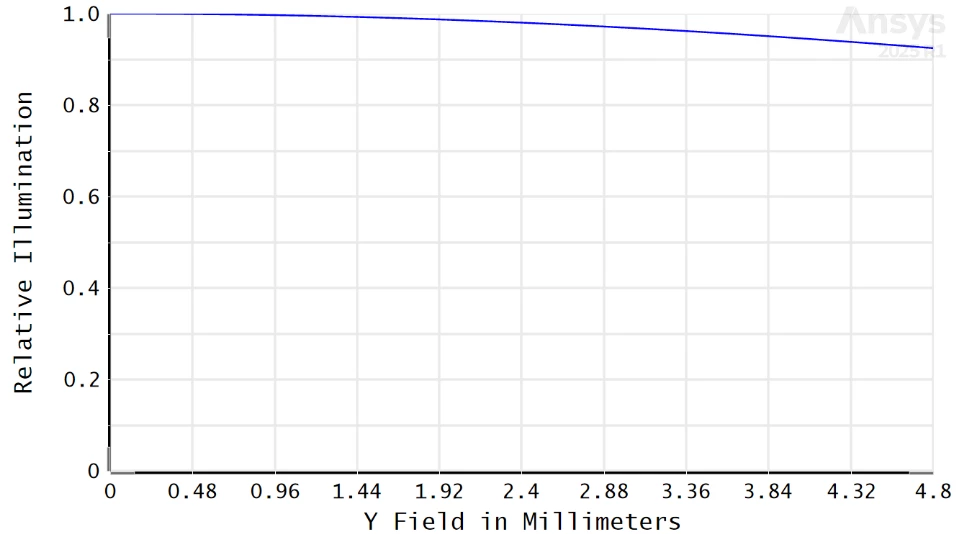
In a real setup, the image given by a sensor is an almost-flat image, with just a small roll-off from the center towards the edges often called “cos4” effect.

My question is : is the Relative illumination tool, and the associated effective F number, well adapted for computing such roll-off profile ?

note that the doc states about  : “The computation method assumes [...] the image surface is a reasonably good conjugate (that is, an image) of the object surface”, so it does not seems to apply. On the other hand, the doc also states “The relative illumination is computed by integration of the effective area of the exit pupil as seen from the image point(s)” which seems like the right thing.

3 replies

MichaelH
Ansys Staff
Forum|alt.badge.img+2
  • Ansys Staff
  • January 9, 2026

Hi Mocquin,

Yes, the RI tool accounts for the roll-off seen with traditional imaging systems as the field increases.  The cos^4 effect in radiometry is an assumption for a perfect imaging system and includes the following considerations: 

  • The angle between the chief ray and the optical axis (cos^1)
  • The inverse square law for the distance between the pupil and the image plane (cos^2)
  • The apparent decrease in pupil size for increased field (cos^1)

Putting it all together, the RI tool takes all these into account (as well as real world considerations like chromatic aberration, vignetting, and polarization); since the RI tool takes into account other considerations, you generally will not see a true cos^4 curve because this is only for a generalized, paraxial, aberration free system.  The actual method uses the exit pupil area in direction cosine space.  The algorithm is laid out nicely in Rimmer’s paper Relative Illumination Calculations available for download on SPIE’s website.


mocquin
Ultraviolet
  • Author
  • Ultraviolet
  • January 12, 2026

@MichaelH

Hi and thank you for your response. My question was specificilay addressing the “no lens” condition, where a blackbody is placed in front of a circular aperture. I actually endedup just doing the verification by comparing the RI from a single aperture VS a paraxial lens with same size.

While exhibiting a nice smooth roll-off, the aperture is different from the one with the paraxial lens: 

Paraxial
Circular aperture

which confirms that the tool does not work for single apertures in front of a blackbody.


MichaelH
Ansys Staff
Forum|alt.badge.img+2
  • Ansys Staff
  • January 12, 2026

Hi Mocquin,

I’m still not sure I fully understood your initial question but I’m glad to hear you have found a solution that works for you.

For others visiting this question, I want to be clear that for a lens-less system, the Relative Illumination analysis is still 100% correct and it does actually converge to the cos^4 approximation from basic radiometry.  To illustrate this point, I have a basic system with a Stop 10mm in front of the image plane and a 5mm EPD:

I use a macro to cycle through fields from 0° to 50° while calculating both the RELI operand as well as the calculating the cosine to the fourth power of the chief ray’s angle of incidence using the following ZPL snippets:

ri = OPEV(OCOD("RELI"), 3, wave, 2, 0, 0, 0)
cos4 = POWR(COSI(OPEV(OCOD("RAID"), NSUR(), wave, 0, 1, 0, 0) * ACOS(0) / 90), 4)

This provides the following table of values:

field ri cos^4 diff
0 1 1 0
5 0.984865 0.984865 0
10 0.940602 0.940602 0
15 0.870513 0.870513 0
20 0.779728 0.779728 0
25 0.674688 0.674688 1E-10
30 0.5625 0.5625 2E-10
35 0.450255 0.450255 1E-10
40 0.344363 0.344363 0
45 0.25 0.25 3.2E-08
50 0.170714 0.170714 1E-08


The reason why using a Paraxial surface changes the RI values in your test is because the Paraxial lens itself changes the chief’s ray AOI with the image plane and it’s angle that radiometry text books refer to when calculating the cos^4 roll-off for free space propagation of a Lambertian source.  The only way to get the Paraxial surface to match free-space propagation is to have the focal length set to infinity.  I have the full ZPL code to generate the table above:

steps = 10		 # number of field points
max_field = 50 # in degrees
wave = 1 # wave number for MFE operands

FORMAT 14.10 # ensure enough precision for difference

# header column
PRINT " field , RI , cos^4 , diff"

# loop through all fields, update system, & calculate RI/cos^4
FOR i = 0, steps, 1
# update field value
fy = (i / steps) * max_field
SYSP 103, 2, fy
UPDATE EDITORS
PAUSE THREADS

# calculate
ri = OPEV(OCOD("RELI"), 3, wave, 2, 0, 0, 0)
c4 = POWR(COSI(OPEV(OCOD("RAID"), NSUR(), wave, 0, 1, 0, 0) * ACOS(0) / 90), 4)

# print results
PRINT fy, ", ", ri, ", ", c4, ", ", ABSO(ri - c4)
NEXT