Question

Problem with Non Sequential component: rays don't go through

  • 27 May 2024
  • 7 replies
  • 121 views

Hi,

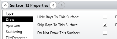
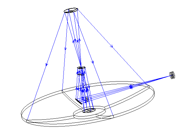
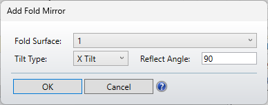
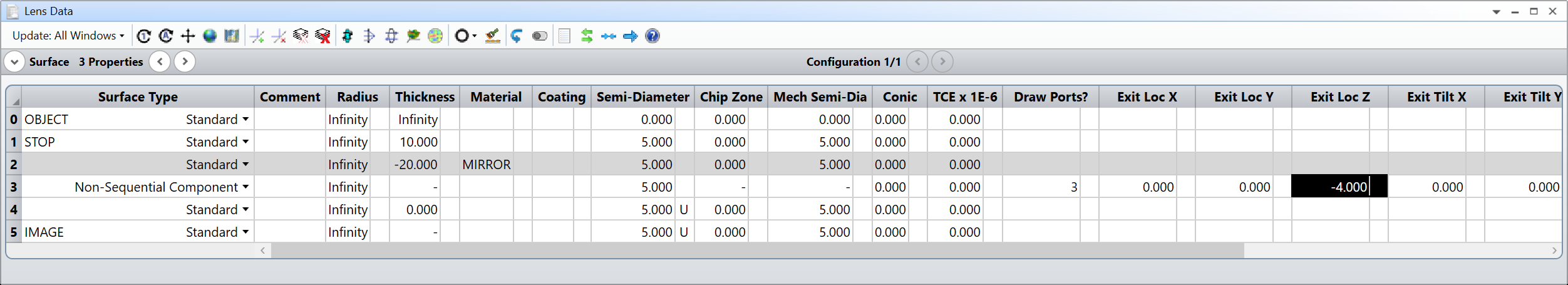
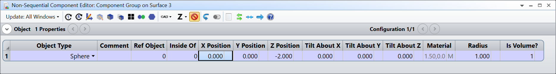
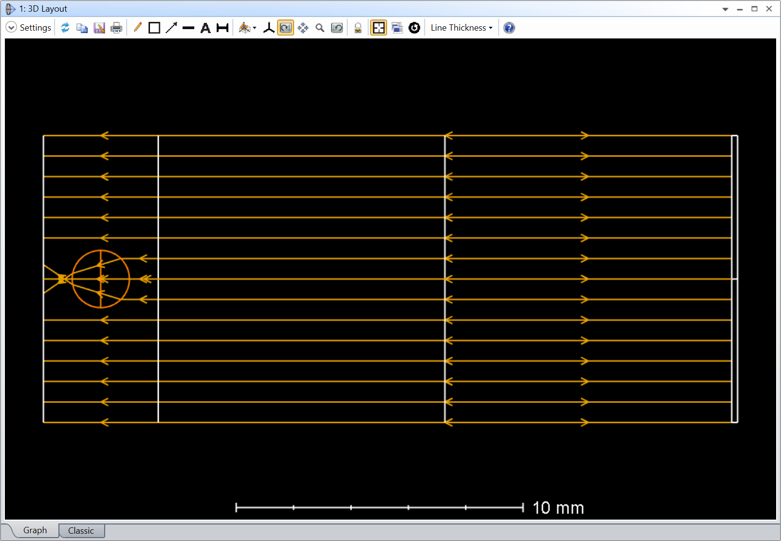
I have a telescope design (sequential mode) in which I tried to insert a non sequential component. In the attached file the telescope model is OK, and at the end (surface 11), I inserted a NSC component, containing nothing for the moment. I can’t figure out why rays are not entering the NSC component and going through…

If anyone can have a look on the attached file, that would be great!

Thanks,

Julien

7 replies

Userlevel 4
Badge

Hi Julien,

Not a solution, but a few settings that may help you debug the system further:

I could get rays to pass by changing the sign of the “Exit Loc Z” to -400 (of course the position is not where you want it). Also, you may want to not skip the rays to the image surface, at least as long as you are debugging.

One setting that may help in the layout window is to fletch the rays, that’s how I saw that the rays where travelling backwards from your entry port:

Regards,

Thanks Ray!

This can help, indeed. What is surprising in this file, is that all rays are going backward! I also noticed that when inserting a paraxial lens, its focal length has to be negative for a convergent lens…


Userlevel 4
Badge

As you start with negative thicknesses, it’s  all “virtual”. If you reverse signs of all thicknesses, radii and polynomial coefficients, you get also a working system.

Damn! You’re right! I’m not the author of the original design, I have no idea why they did it that way…

Is there a function to change all the signs automatically? The file I shared is only the telescope (13 surfaces), but I’m working on  several more complex files with a full instrument after the Nasmyth Focus, representing more than 50 surfaces, with complex coordinate breaks, and even automatic movements. It will be a nightmare to invert everything correctly!

Thanks anyway

Julien

Userlevel 4
Badge

Mirrors change the axis orientation. Most likely the system was built with a mirror at the beginning and it was removed from the model. One automatic way to reverse is to add a mirror using Zemax tool for it (add fold mirror) which will reverse signs where needed and delete the added surfaces.

First add a new surface after the object, before the stop. Then add a fold mirror using this new surface:

You will now have 2 coordinate breaks around that new dummy surface. Note that all signs have been reversed.

Finally, just deleted the 3 new new surfaces and the system is now having real rays. And that solves the original problem.

It works! You saved my day!

I really don’t know why someone would have imagined a giant fold mirror at the top of a 40m telescope...

Thanks a lot,

Julien

Userlevel 7
Badge +2

Hey @Julien Dejonghe and @Ray 


I briefly looked at your file and also noticed you have a positive Z Position of your Null Object in the Non-Sequential Component Editor. I’m not totally sure, but I did a few test and I think that if you arrive from a mirrored space into the Non-Sequential Component Surface, you might have to define your positions in the Non-Sequential Component Editor differently. I tried to make a simple example of what I mean with a collimated sequential beam partially going through a non-sequential sphere.

I have put a mirror such that I have to use negative thicknesses before entering the Non-Sequential Component Surface. This is the result.

If I had put the Sphere at Z Position = 2.000. The Sphere would be on the wrong side of the Entry Port somehow and doesn’t interact with the rays obviously.

I don’t know what’s the good practice in this case, perhaps we could rotate the Non-Sequential Component Surface as well? I’m attaching my file for reference.

Anyway, just something I noticed.

Take care,


David

Reply