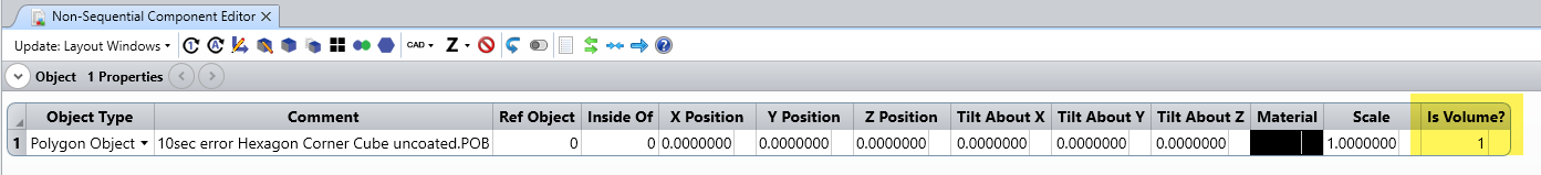
I am struggling creating a polygonal volume with a given material using the Zemax Part Designer Utility. Whatever I tried, the shape seems to remain hollow. Did anybody figure out how to specify that the shape is bulky !
Thank you ,
Regards,
Pascale
Best answer by Sandrine Auriol
Hi Pascale
I have attached the model with 2 configurations just to be sure we have the same starting point.
Description
Total Power
Lost energy due to errors
Configuration 1
No cylinder
Source starts inside the Hexagon
0.985W
0.004W
Configuration 2
Cylinder
Source starts inside Cylinder and then Hexagon
0.838W
0.15W
So the difference comes from errors in the ray tracing.
If I ran again a ray trace in configuration 2 and untick Ignore Errors, the software says:
So actually it may be that I need to adjust the non-sequential settings for the raytracing in the 2nd configuration. For example, using Simple Ray Splitting solves the issue.
So I guess I would just go for the 1st simulation since it is simpler.
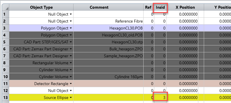
I checked your file and it seems like you need to define the front and the back for that object to be changed into a volume. I also moved your source as you need to tell the software when a source starts inside a volume, and the volume has to be defined before the source in that case.
Thank you. Effectivelly, this was a big mistake not to put the source inside the object. Sorry about that.
However, taking care of this important point, I went further into the different ways to model a polygonal and I am surprise to obtain differents results.
I abandonned the approach of Polygon Object because this is not convenient to define the front and back and then the results are very strange and not consistent at all with this approach.
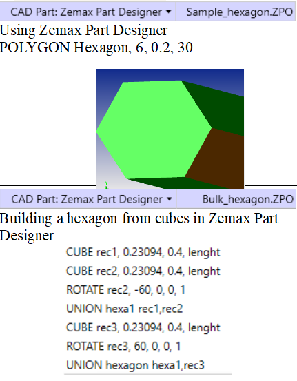
I focalised to the Zemax Part Designer with two approaches.
I placed a source of 1W size 60x60µm2
1 inside the polygon
2 inside a cylinder ( 160µm diameter ) placed inside the polygon and of the same material as the polygon
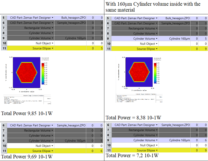
and I collected the total power at the end of the polygon
I would expect that there are no difference between the results
1 for both of the polygon modeling => there is a small difference of about 1.5% ( repeatable not due to unsufficient rays number)
2 with and without the cylinder since there is a material continuity. = > there is an important difference with and without the cylinder and according to the polygon modeling approach.
I wounder what is missing in the approach to properly model the continuity of the material ?
I have attached the model with 2 configurations just to be sure we have the same starting point.
Description
Total Power
Lost energy due to errors
Configuration 1
No cylinder
Source starts inside the Hexagon
0.985W
0.004W
Configuration 2
Cylinder
Source starts inside Cylinder and then Hexagon
0.838W
0.15W
So the difference comes from errors in the ray tracing.
If I ran again a ray trace in configuration 2 and untick Ignore Errors, the software says:
So actually it may be that I need to adjust the non-sequential settings for the raytracing in the 2nd configuration. For example, using Simple Ray Splitting solves the issue.
So I guess I would just go for the 1st simulation since it is simpler.