I am using a source diode which is propagating the rays in XY plane.I want to define TE polarisation for the source diode.
So in this case can someone suggest me that which axis reference should I assign in the system?
Also, if the diode laser emits at a position 54° from the negative Y axis and 36° from negative X axis, then how can I assign the TE polarisation to the current source diode??
King regards
Akhil
Best answer by Jeff.Wilde
Hi Akhil,
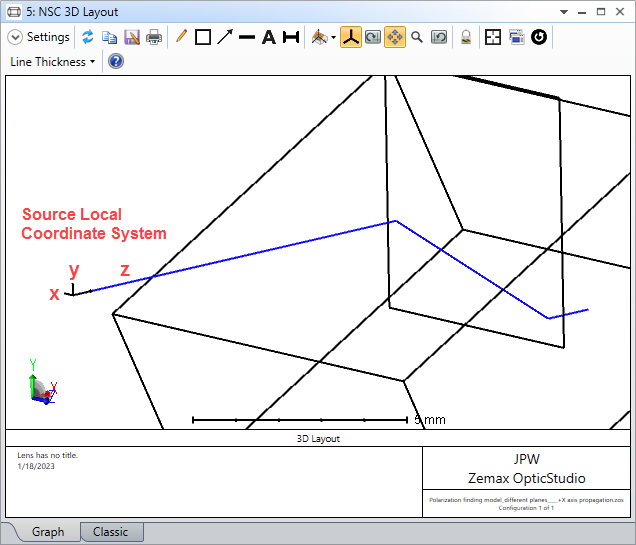
The polarization setting can be a little confusing. Let me see if I can help. In your case, the source is emitting a set of identical rays that propagate along the source’s local z-axis.
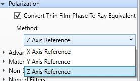
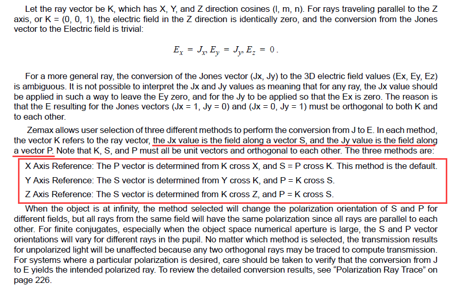
You have Jx = 1, Jy = 0. As noted in the help documentation:
Therefore, for Jx = 1, you have defined the polarization to be along the S direction. But what exactly is the S direction? In general, it depends on the reference method, but we’ll see that in your particular case all three options produce the same result. Note that X, Y and Z are the local axes for the source. The K vector is along Z.
X-axis reference: P-direction is K cross X = Y, and S = P cross K = Y cross K = X. So, with this choice of reference, you have the S-direction along the source’s local x-axis.
Y-axis reference: S-direction is Y cross K = X. So again, you have the S-direction along the source’s local x-axis.
Z-axis reference: S-direction is K cross Z = undefined (because K is along Z). So, the S-direction defaults to the X-axis ref case, namely along the local x-axis.
So all three reference cases yield the same polarization state. In your model, Jx =1 (or S-polarization along the local x-axis) corresponds to S-polarization incident on the input face of the rectangular volume. If you want P-polarization incident on the rectangular volume face, then set Jy = 1, as can be confirmed by going through a similar exercise.
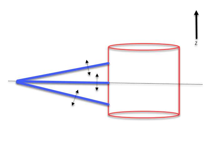
For a more general case, if you want to see how a different choice for the reference method affects polarization, take a look at a diverging set of rays. You can use the Polarization flag on the Detector Rectangle to see how the polarization state varies spatially. Here is an example in which I modified your source to have 25 degrees of half-angle divergence in both x and y, and moved the detector closer to the source (so the rays do not hit the rectangular volume). I also reoriented the detector so that its local coordinate system is aligned with the source’s local coordinates.
For both the X-Axis and Y-Axis reference settings, the rays are predominantly polarized along the source’s local x-axis for the reasons described above -- specifically, the detector reports about 93% of the power being x-polarized. Note, with the detector’s Polarization flag = 0, the total power is 97%, so ~3% of the light simply misses the detector because some of the rays have large angles. The remaining 4% is essentially z-polarized.
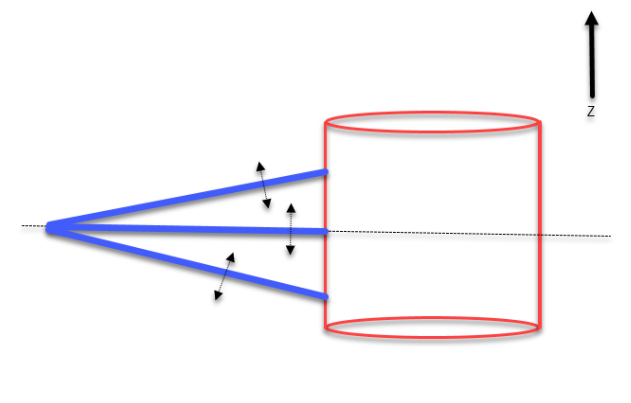
However, when using the Z-Axis reference, the polarization state of the off-axis rays changes, as shown here:
In this case, only about 48% of the light is polarized along the x-axis. I’ve attached this modified model. You can play around with the source and detector settings to see other cases.
I’m sorry that I missed your question at the end of your previous post. To answer it here:
I believe that you’d want to use the same setting I proposed: Y Axis Reference with Jx = 1 / Jy = 0. This will ensure that the electric-field component is pointing perpendicular to the X-Y plane.
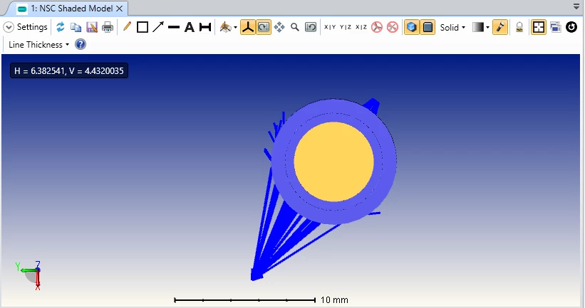
I want bit more clarification about polarization in zemax. In the below attached image, I assigned divergence of the diode as 31. So that not all the rays that propagated from the single source diode is TE polarised if I set Jx=1 and Jy=0. I cross checked and verify this with some other simulation model.
So even though I set the polarization of the source diode defined (s- polarized), not all rays that emit from the source should have the same polarization. Do you have any suggestion for me to make the polarization of the every single ray that emits from a single source uniform??
Yes, that is correct for rays that are out of plane. From the figure, it wasn’t clear to me that the rays are diverging in Z also. In that case, the diverging rays will not be parallel to the object boundary.
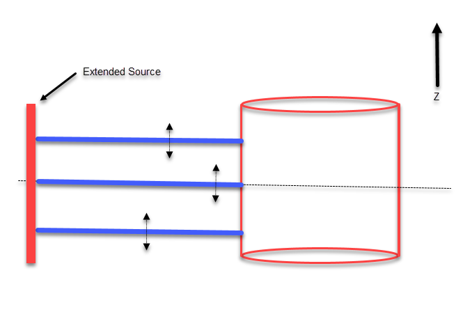
There is not a built-in way to change polarization with angle from a source, unless you create your own source DLL which would take some significant effort. One alternative is: instead of a point source, you could use an extended source in the Z direction:
I want a source exactly polarized like you mentioned in the previous answer.
But in my zemax file, it is not happening like this. I can explain that with a simple zemax model without getting more complicated.
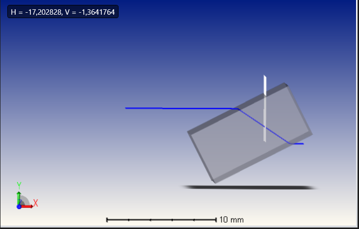
In the botton design I have a single light ray travells in the X axis direction which is then transmitted through a surface. Then the ray is hit on a detector. The trasmission % of the ray through the surface for s and p polarisation is also included below. So from the detector power value, I can found out the polarization of the ray.
I assign Jx=1 and Jy=0 . As far as I understood about the Jones vetor, the polarization should be S for Y axis reference and P for Z axis reference. But in my case, the power value in the detector shows the same for both axis of reference. It even shows the same for X axis reference!!
I thing figuring out a solution for this will solve my problem. Can you have a look on this. I attached the simulation file along with this for better understanding.
I am facing a problem with the axis reference when assigning a polarization.
I assign Jx=1 and Jy=0 . As far as I understood about the Jones vetor, the polarization should be S for Y axis reference and P for Z axis reference when the ray is travelling in x axis.
But in this case, there is no change in the incomng polarization value if I change the axis reference (I confirmed it by measuring the transmission % of the rectangular block, which is different for s and p polarization). Can someone suggest me why the axis of reference make no changes here??
The polarization setting can be a little confusing. Let me see if I can help. In your case, the source is emitting a set of identical rays that propagate along the source’s local z-axis.
You have Jx = 1, Jy = 0. As noted in the help documentation:
Therefore, for Jx = 1, you have defined the polarization to be along the S direction. But what exactly is the S direction? In general, it depends on the reference method, but we’ll see that in your particular case all three options produce the same result. Note that X, Y and Z are the local axes for the source. The K vector is along Z.
X-axis reference: P-direction is K cross X = Y, and S = P cross K = Y cross K = X. So, with this choice of reference, you have the S-direction along the source’s local x-axis.
Y-axis reference: S-direction is Y cross K = X. So again, you have the S-direction along the source’s local x-axis.
Z-axis reference: S-direction is K cross Z = undefined (because K is along Z). So, the S-direction defaults to the X-axis ref case, namely along the local x-axis.
So all three reference cases yield the same polarization state. In your model, Jx =1 (or S-polarization along the local x-axis) corresponds to S-polarization incident on the input face of the rectangular volume. If you want P-polarization incident on the rectangular volume face, then set Jy = 1, as can be confirmed by going through a similar exercise.
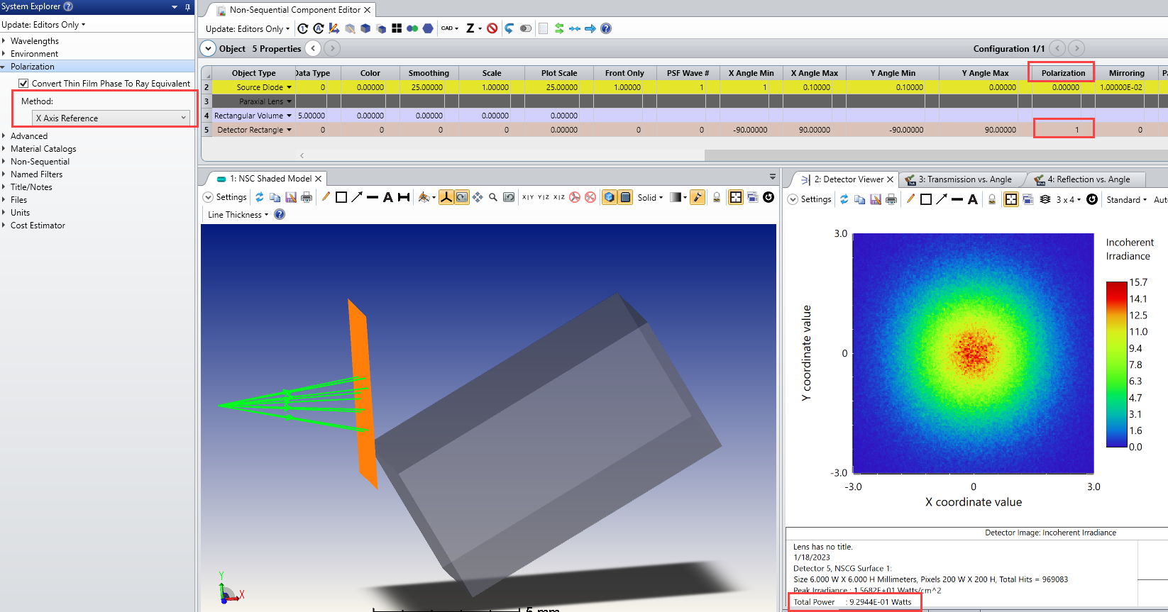
For a more general case, if you want to see how a different choice for the reference method affects polarization, take a look at a diverging set of rays. You can use the Polarization flag on the Detector Rectangle to see how the polarization state varies spatially. Here is an example in which I modified your source to have 25 degrees of half-angle divergence in both x and y, and moved the detector closer to the source (so the rays do not hit the rectangular volume). I also reoriented the detector so that its local coordinate system is aligned with the source’s local coordinates.
For both the X-Axis and Y-Axis reference settings, the rays are predominantly polarized along the source’s local x-axis for the reasons described above -- specifically, the detector reports about 93% of the power being x-polarized. Note, with the detector’s Polarization flag = 0, the total power is 97%, so ~3% of the light simply misses the detector because some of the rays have large angles. The remaining 4% is essentially z-polarized.
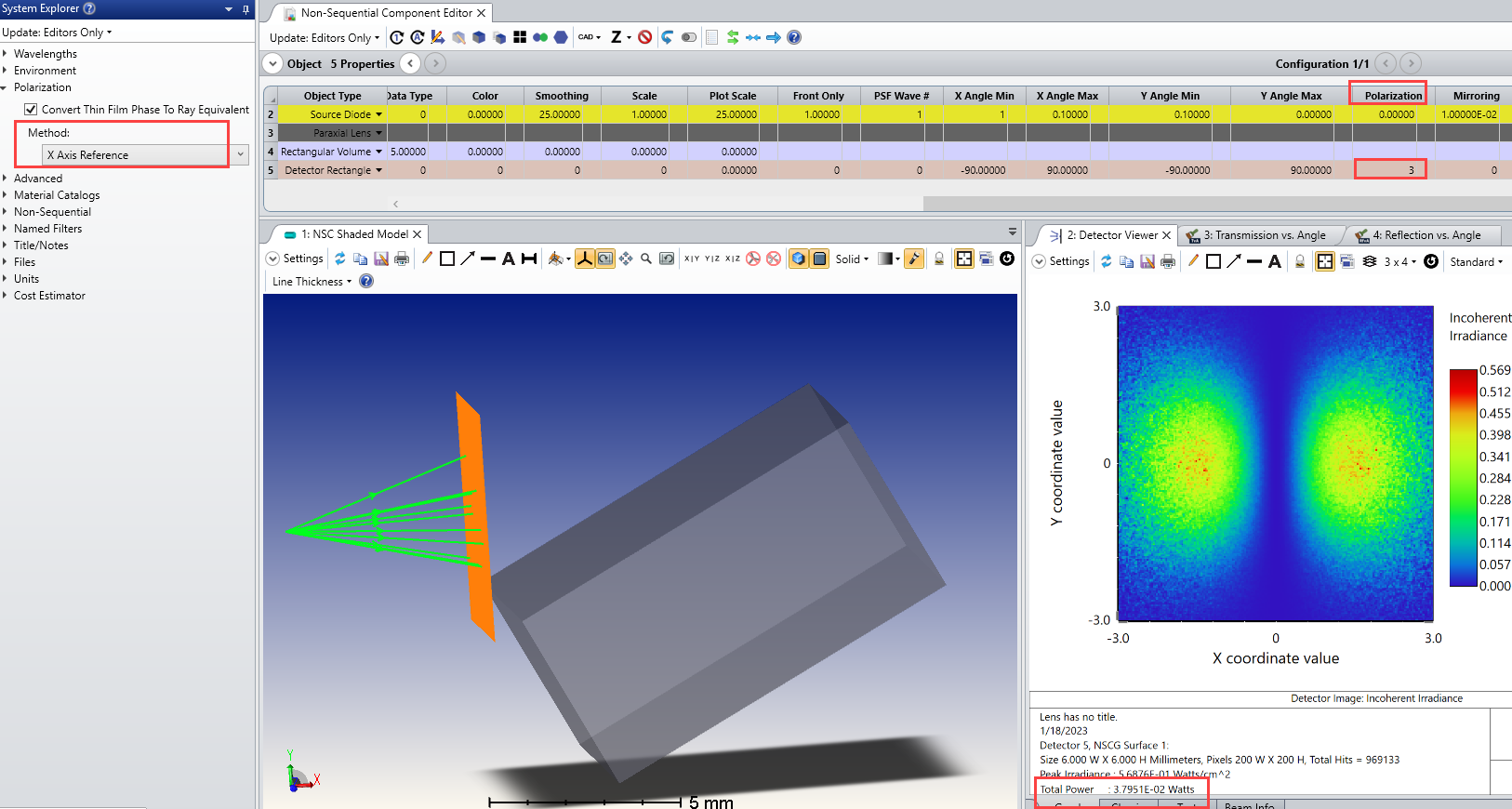
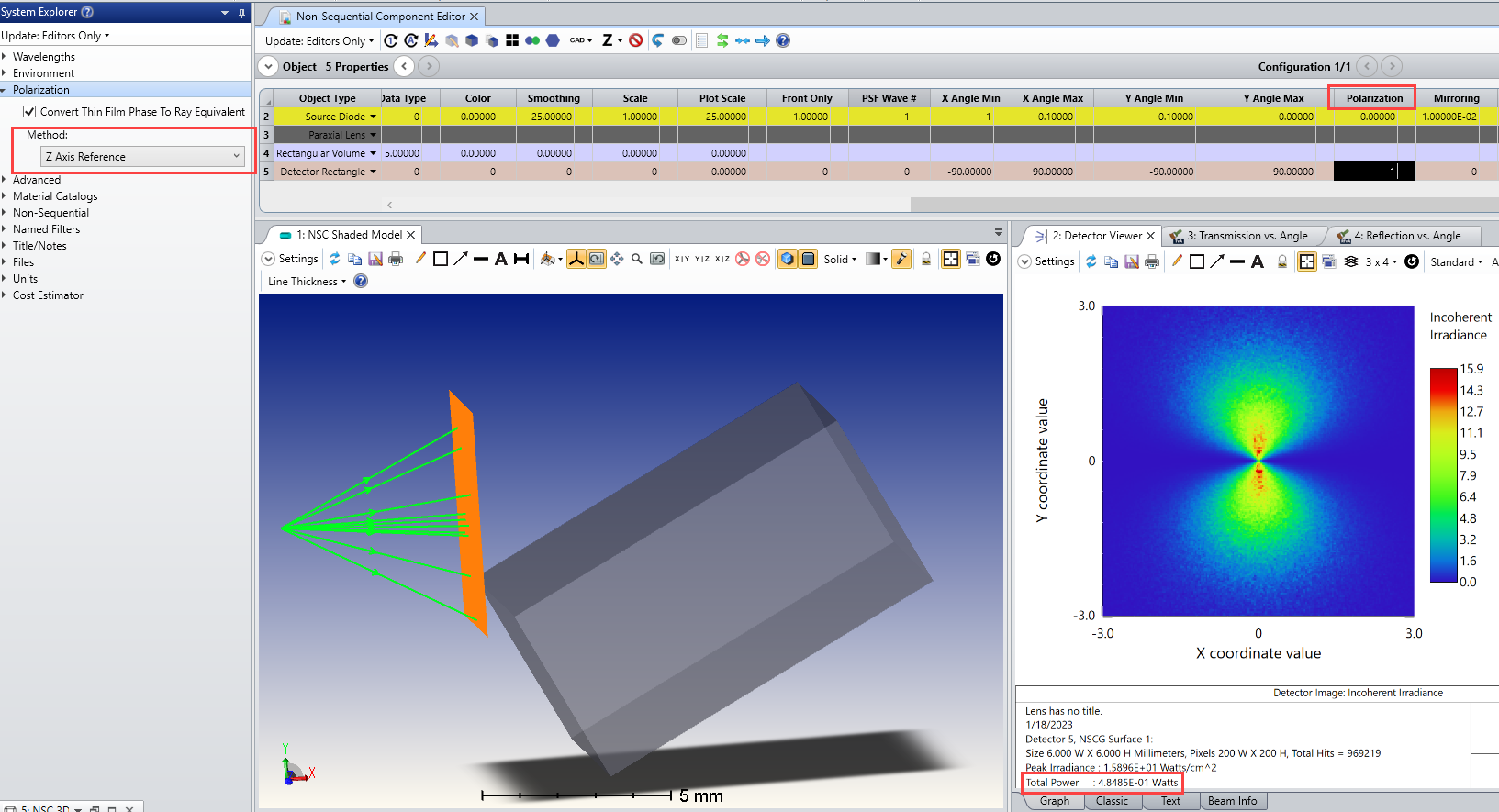
However, when using the Z-Axis reference, the polarization state of the off-axis rays changes, as shown here:
In this case, only about 48% of the light is polarized along the x-axis. I’ve attached this modified model. You can play around with the source and detector settings to see other cases.
Your answer helped me a lot to clarify about the polarization in zemax. But I still don’t understand some points.
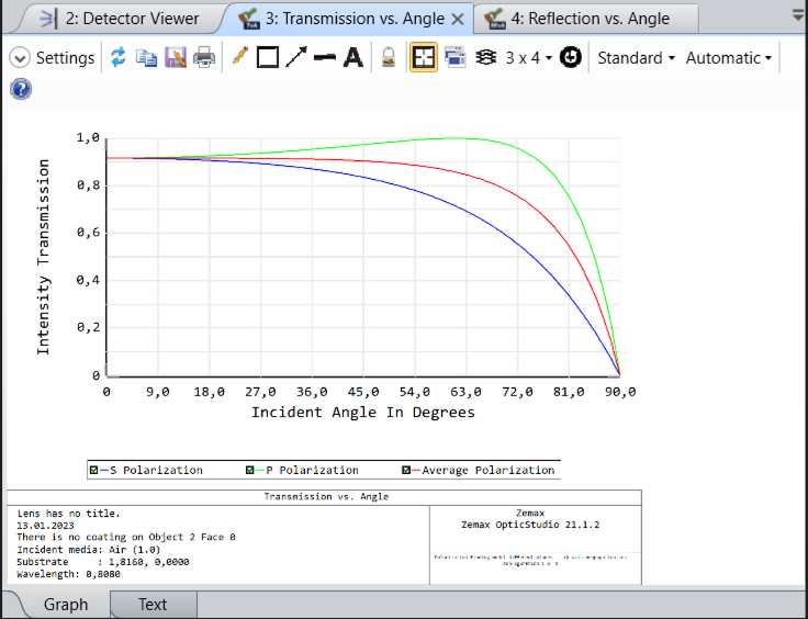
The bottom image shows the ray propagating in the local z axis and has s- polarization (Jx=1).Which is then passed through a rectangular block and then a detector is placed inside the rectangular block to measure the transmission % of the rectangular block. The detector rectangle has polarization flag 0 means it will detect everything that comes through.
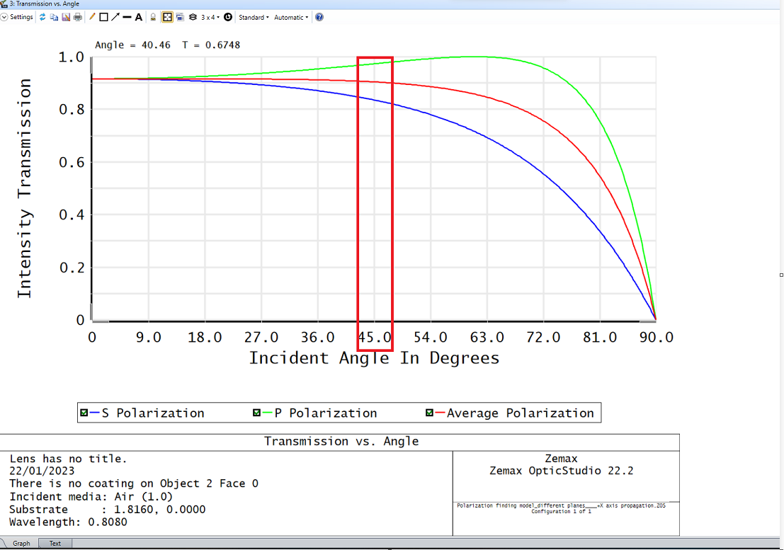
The rectangular block has different transmission for s and p polarization at different incident angles.So at 45° incident angle , s polarization has 83% and p polarization has 97% transmission.
Initially I assigned the local axis for the source, rectangle and detector in the same way as in the above image. Then I got 97% power on the detector eventhough I assign s polarization. Then I rotated the local axis of the rectangle by 90°.
After changing only this and run the simulation , I got 83% power on the detector. This means the polarization is changing eventhough I didn’t do anything in the source!!
So how can I prove that Jx=1 means s polarization by considering this whole setup (the source, the rectangular block and the detector)??
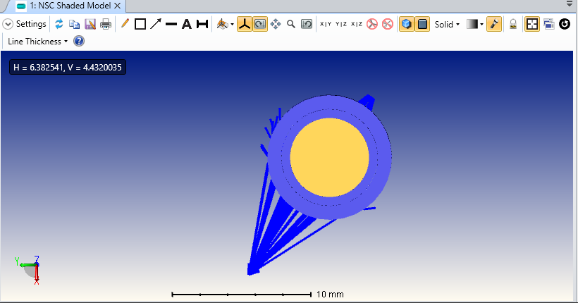
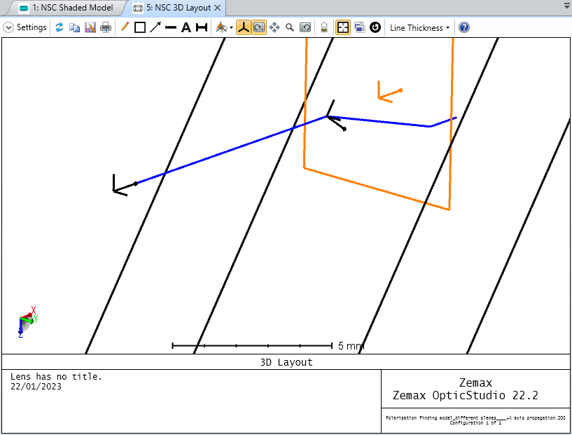
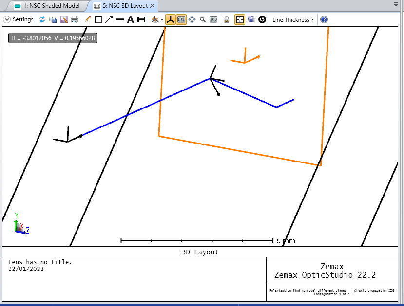
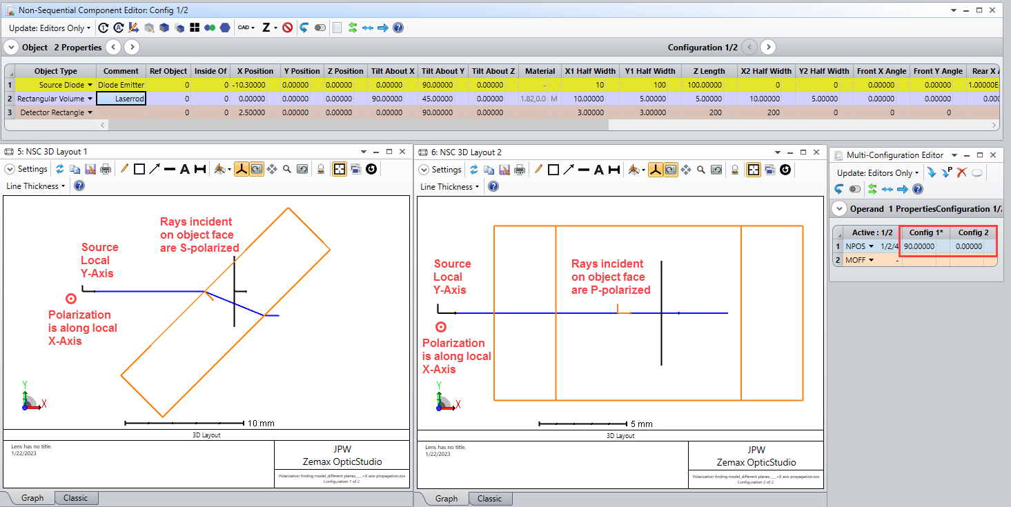
By rotating the rectangular volume about its local x-axis, you are changing the plane of incidence, going from S-polarization (with Tilt-X = 90 degrees) to P-polarization (with Tilt-X = 0 degrees). Here are views of the two configurations from the same perspective in the global coordinate system:
So, in one case your detector is measuring the S-polarized transmission, while in the other case it’s the P-polarized transmission.