Solved

Photoluminescence Layout Rays in NSC 3D Diagrams

  • July 18, 2022
  • 2 replies
  • 124 views

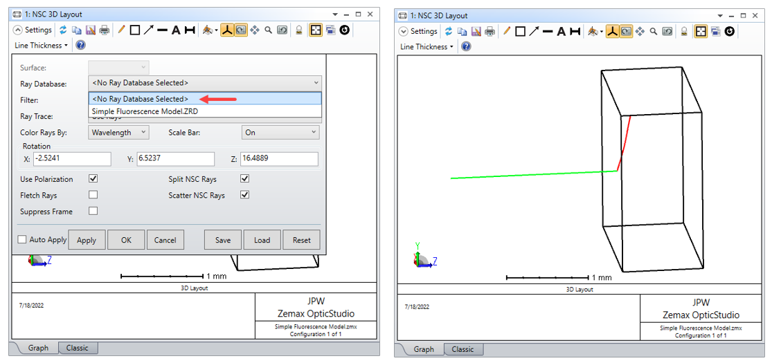
In modeling a photoluminescent material in OpticStudio, when I raytrace with ONE Analysis Ray and ONE Layout Ray, the NSC 3D diagram looks like this:

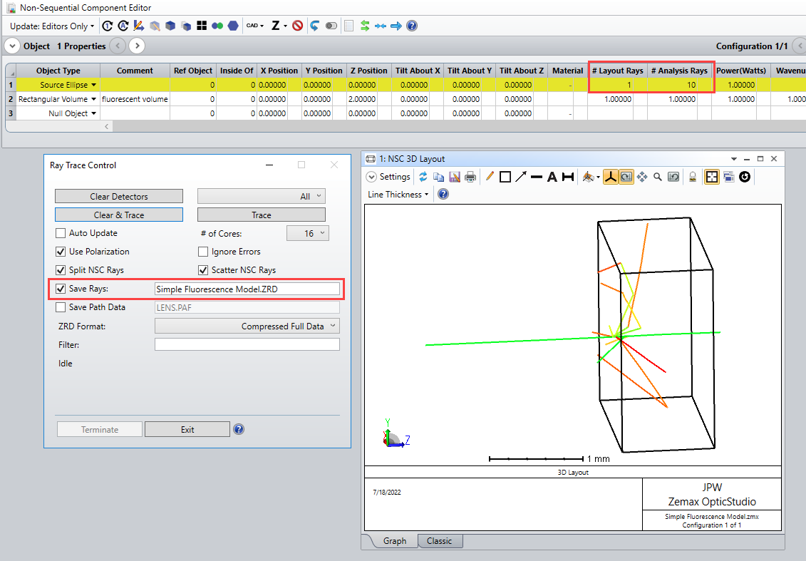
But when I raytrace with TEN Analysis Rays and ONE Layout Ray, the NSC 3D diagram looks like this:

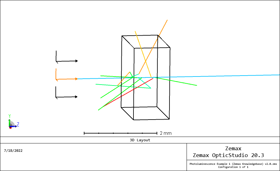
This seems to be presenting more than ONE Layout Ray despite the unchanged Entry of ONE (1) in the Source Object Property Box for Layout Rays.

Can someone explain this?

Best answer by Jeff.Wilde

Did you happen to run the Ray Tracer with the option to “Save Rays” selected?  If so, then your layout plot may simply be displaying the rays in the saved ZRD file.


If so, then you can easily stop using this file and go back to a single ray layout:


2 replies

Jeff.Wilde
Luminary
Forum|alt.badge.img+3
  • Luminary
  • Answer
  • July 19, 2022

Did you happen to run the Ray Tracer with the option to “Save Rays” selected?  If so, then your layout plot may simply be displaying the rays in the saved ZRD file.


If so, then you can easily stop using this file and go back to a single ray layout:


Thanks, Jeff. That was exactly what was happening. The default had changed in the 3D Layout without my knowledge, probably when I loaded the latest S/W update.