Solved

Parabolic Mirror Setup

  • 4 December 2020
  • 8 replies
  • 1093 views

Dear Zemax Team,


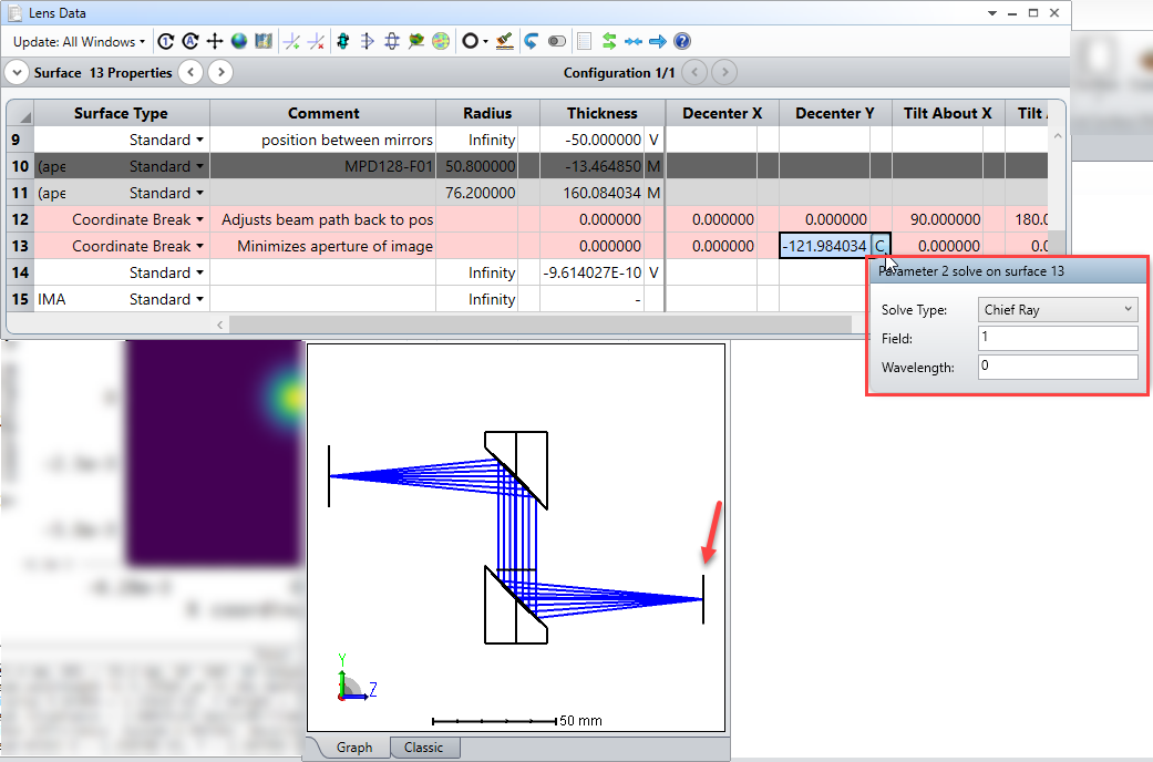
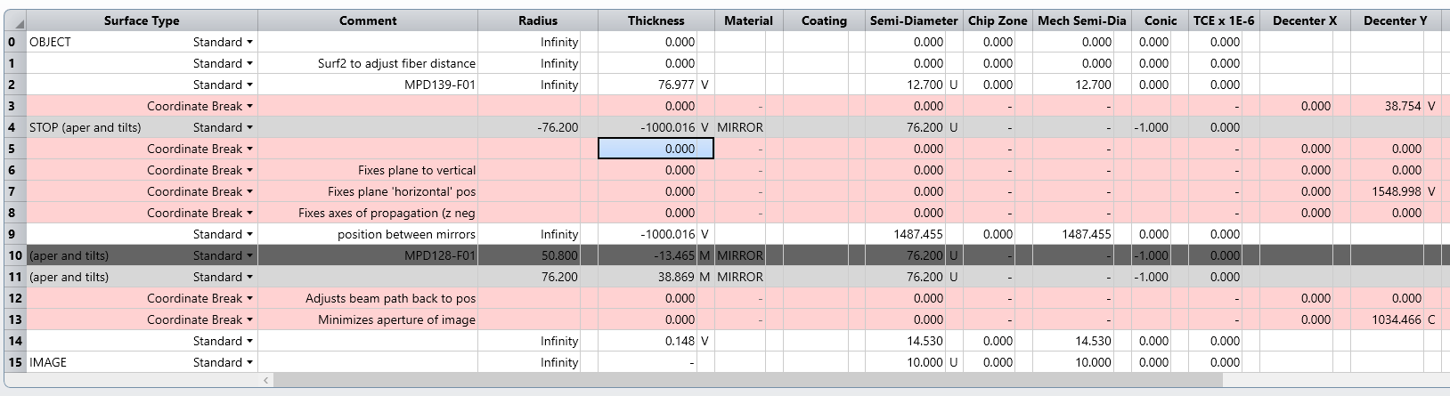
I would like to model and optimize an optical system that utilizes two parabolic mirrors.


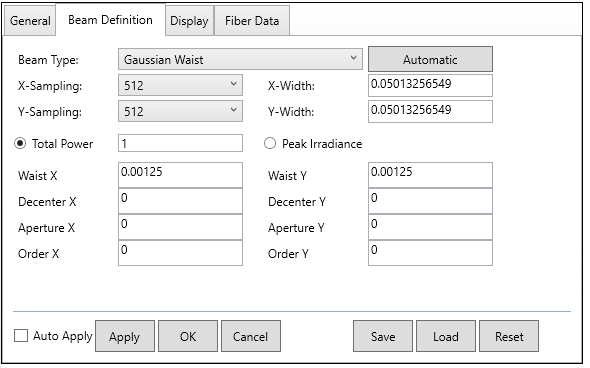
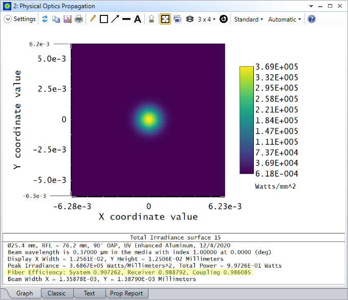
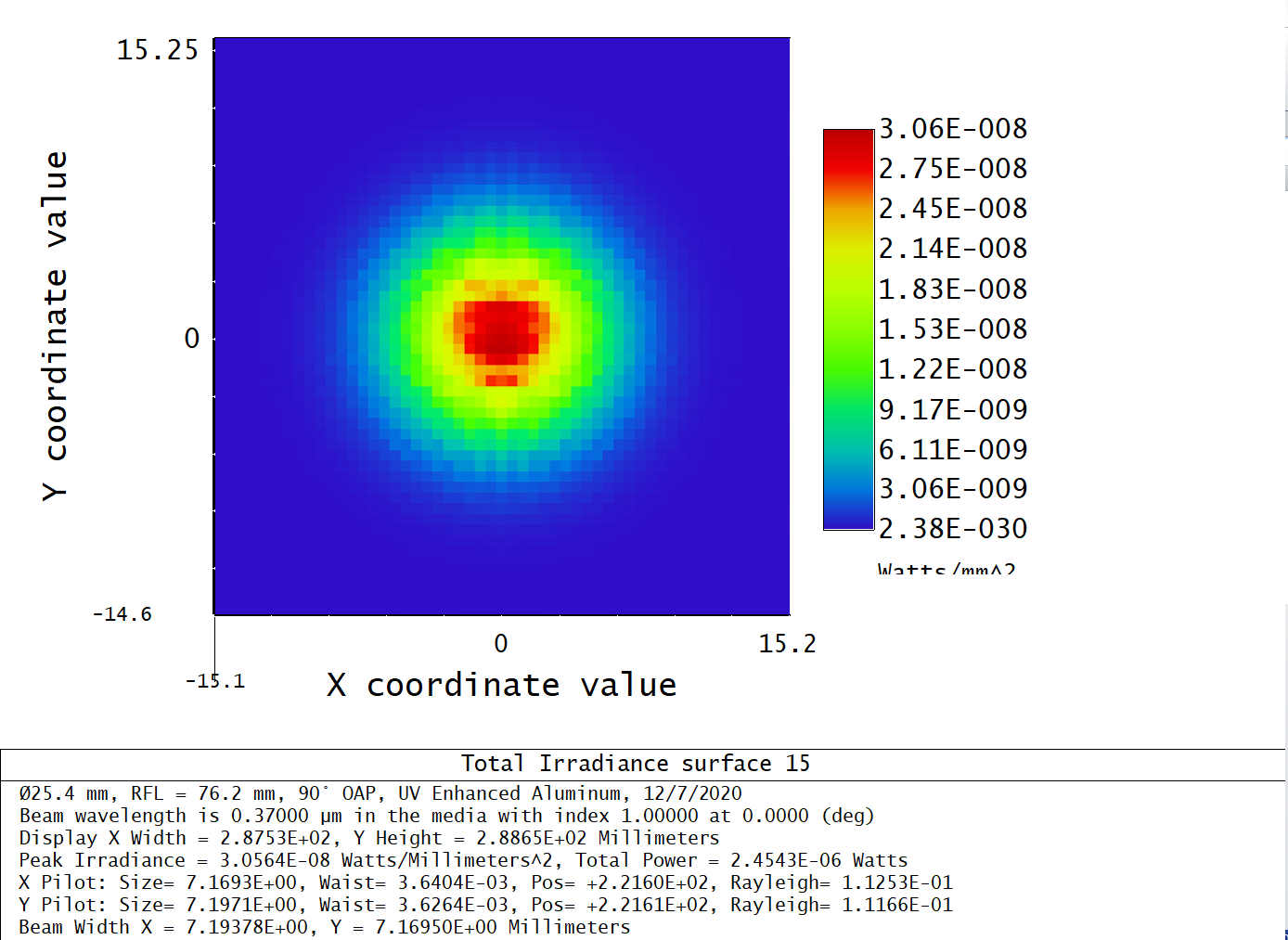
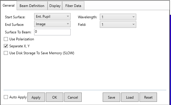
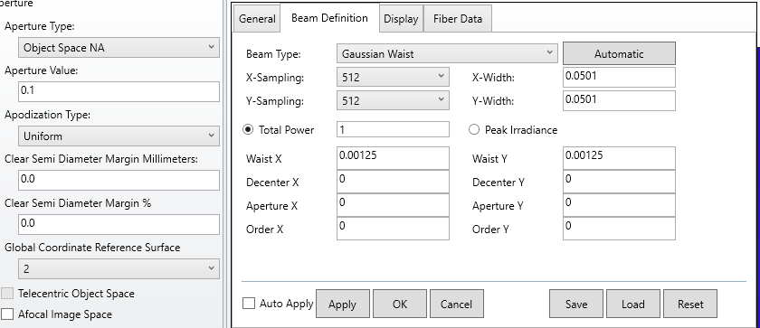
The mirrors would be placed in such a way to create an approximate 1:1 imaging system from an optical fiber (mode size ~ 2.5 um). I would like to know the position tolerancing for the two mirrors in order to minimize the spherical and chromatic aberration of two colors, 370nm and 780 nm. Furthermore, it would be ideal if the system works with the Physical Optics Propagation tool to visualize the beam and to predict the expected fiber coupling efficiency.


I have been able to create the system such that it looks appropriate in the ray tracing system, but the optimization feature and the POP produce results that are quite unexpected. I expect this is attributed to user error as opposed to the 'real' results.


I have attached my working zemax file for reference.


Thank you for all your help!


Regards,


George

icon

Best answer by Angel Morales 4 December 2020, 20:13

View original

8 replies

Userlevel 5
Badge +1

Hi George!


Thanks for your post on the forums here. When you say you're running into optimization issues, what specifically is the problem that you're having? I noticed that if I just ran optimization from your starting point and with your current merit function and variables, the local minima it finds has quite a large distance between the OAP reflectors:


If this is what you're referring to, then I think you'll need to add some constraints into the merit function that will limit the distance that the two OAPs can have between them. Some operands you could refer to are CTGT/CTLT (Center Thickness Greater Than/Less Than). That way, you could limit the thicknesses of specific surfaces (in the case of negative thickness, you'll want Greater Than due to the sign convention).'


As for the POP setup, what settings did you have that produced unexpected results? You'll want to be sure to properly define your Beam Definition tab to define the input mode of interest, as POP won't really look at your System Explorer...Aperture tab to define what the input light will be. As a test, I modeled a Gaussian Beam of waist 0.00125 mm (to model your 2.5um diameter) -- I also used the same definition for the Fiber Data tab, as I assumed the same mode field diameter was desired in this 1:1 system:


Lastly, I noticed your Image Plane was decentered from your Chief Ray, perhaps due to your Coordinate Break definitions. If you'd like, you can align the Image plane to your chief ray using a Chief Ray solve on Coordinate Break surfaces (I used Surface 13 as that only had a Decenter Y term already):


Please let us know how these thoughts work out for you!


~ Angel

Hello Angel,


Thank you for the quick response. A few questions about the results you posted as I am having trouble reproducing them on my end.


When I try to optimize my system (Object space NA .1), my 3D layout produces a non-physical result, shown below.


Do you know what maybe causing the beam to want to travel through the first optic? The output optimized lens file I get is attached.


Also, when I try to utilize the POP and reproduce the beam size you achieve, I see results quite different from your spot. The spot below is shown from the original lens file as the optimized file produces a non-existent spot.


The settings I am using are primarily default. Is there something different here that I am missing?


The spot I am trying to optimize in reality is a 2 um waist and I am trying to couple into a 2.6 um fiber. I think these are minor adjustments from my first post, but I wanted to clarify in case that made a substantial difference. 


Please let me know your thoughts and thank you for helping me troubleshoot this problem.


-George

Userlevel 6
Badge +2

Hi George,


I have downloaded your file and I have the same results as Angel after optimization. Can you let me know how you are optimizing the system? Are you using the local optimizer, or Hammer? I am attaching the system I have after using the local optimizer. Please open it and let me know if you see the same layout as is shown in Angel's screenshots. 


Regarding your questions about POP - I'd like to take a quick step back and ensure this is the correct direction. POP is not the only method for performing fiber coupling analysis. Is there a reason you want to use POP over, say, Huygen's PSF (visualization) and the Fiber Coupling tool under the Analyze tab? In general, POP can be challenging to set up, and these other tools will provide a comparable result in many cases. For your reference, we have two articles on this topic here and here


Best,


Allie

Hello Allie, 


I would like to revisit this thread regarding POP and fiber coupling.


The intended purpose of my system is to simulate the coupling efficiency of an output mode with a Fabry-Perot interferometer. As the Gaussian mode of an optical cavity is similar to a single mode fiber, I intended to use the fiber coupling within the POP to estimate how much power will couple to the optical cavity. My main concern is how the spherical aberration will decrease my overall coupling efficiency and if the POP results are feasible when I put these optics together.


I have since moved on from the dual parabolic mirror approach above and instead am using a single reflective collimator combined with an achromatic lens. I have noticed there is considerable aberration on the edges, resulting in a spot that is far from diffraction limited. However, the POP coupling efficiency remains high at 70-80% for my two colors. Can I trust this value or am I missing something that disconnects the fiber coupling tool and the POP's calculation?


Thank you for all of your help,


George

Userlevel 5
Badge +1

Hi George,


Thanks for your follow-up post here!


Unfortunately, it looks like you've shared your .ZDA file, which is the session file which accompanies .ZMX files and contains information like which analyses were open, what settings they were defined at, etc. Would you be able to re-share your system as a .ZAR (OpticStudio's archive file format)? You can create the archive file in the File tab...Create Archive.


As for why the coupling efficiency is different from your expectations, it's hard to say why without looking at your file. One thing I can think of is that you have likely set your Apodization Type to Gaussian in the System Explorer. This would concentrate more energy to the center of your beam as opposed to another type such as Uniform. Therefore, the aberration effects at the edge of your pupil may not have as large of an effect in coupling as you are expecting from an analysis like Spot Diagram.


Let us know if you're able to share your file, and we'll be happy to provide more thoughts and discussion as needed!


~ Angel

Userlevel 5
Badge +1

Hi again George,


Sorry, I've just re-read your post, and realized you were comparing POP results to ray-based results. My apologies -- I think I still need my morning coffee...


If your ray-based results are more pessimistic than POP, then it's like you have not yet set your Apodization Type to Gaussian. Changing this setting would bring both analyses on par with each other. The reason is POP will make no consideration to your Apodization Type settings in the System Explorer. The beam you define in the Beam Definition tab is what will get sent out, and this could be different from how your rays are set up. Therefore, you'll want to ensure that your rays are defined in a way that match with POP settings. There is some discussion on this forum thread (about halfway down) which covers this. You can also take a look through this article here.


Thanks again, and let us know if you have any more questions!


~ Angel

Hello Angel,


Thank you for the quick reply. To keep this discussion going here is the .ZAR file you requested.


I notice you can change the apodization in the system explorer which will change the spot diagram and the fiber coupling output. Is there a similar feature in the Physical Optics Propagation?


Cheers,


George

Userlevel 6
Badge +2

Hi George,


Thank you for sharing your file.


In POP, the beam has a waist of 0.002mm and is defined as gaussian waist. This definition is for 1/e^2. For WL=0.37um, that gives a NA of 0.06 at 1/e^2. 


So you could set NA=0.06 with an apodization factor of 1. Usually we want to trace rays with lower energy, so for example for an apodization factor of 4, that gives a NA of 0.12.


In POP, I see that the beam starts at the entrance pupil. I think it should start at surface 1 to be equivalent with the ray-tracing. I also don't think you need to separate X and Y. This is for very astigmatic beam where different propagation methods are needed for X and Y planes.


I am finding a coupling of 32%. See attached.


Sandrine

Reply