optical coherence tomograpgy

  • 22 May 2021
  • 1 reply
  • 171 views

Dear engineers:


    According to the article 'How to model an Optical Coherence Tomography System' provided by Zemax, I try to simulation OCT. During the processing, I come across some problems.


    As you can see, the article shows the result is clear and perfect. But the result is terrible in my system. I don't know the reasons. Can you help me to solve the problem?


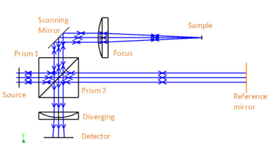
 The result provided by Zemax


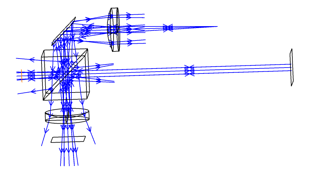
The result provided by me


1 reply

Userlevel 6
Badge +4

Hello Yuxin,


It appears to me that in your layout we see Fresnel reflections from glass-air interfaces that are not seen in the Zemax model. These are probably very low intensity rays. You can neglect them by opening the System Explorer and setting the Non-sequential / Minimum relative ray intensity to some reasonable value, like 0.05. This means any ray segment that has fallen in intensity to below 5% of the launch intensity will be terminated and not used in calculation or display. You can make sure it is not significantly affecting the simulation by noting the Lost Energy that is reported by the ray trace dialog. It might help to put AR coatings on appropriate surfaces.


I looked at your ZMX file, but it does not reproduce the layout image you attached. If my comments don't help, you might recreate the layout shown and then attach the design as a Zemax Archive (ZAR) file. It can be created by using File / Save As / ZAR. That way your layout is included.


Kind regards,


David

Reply