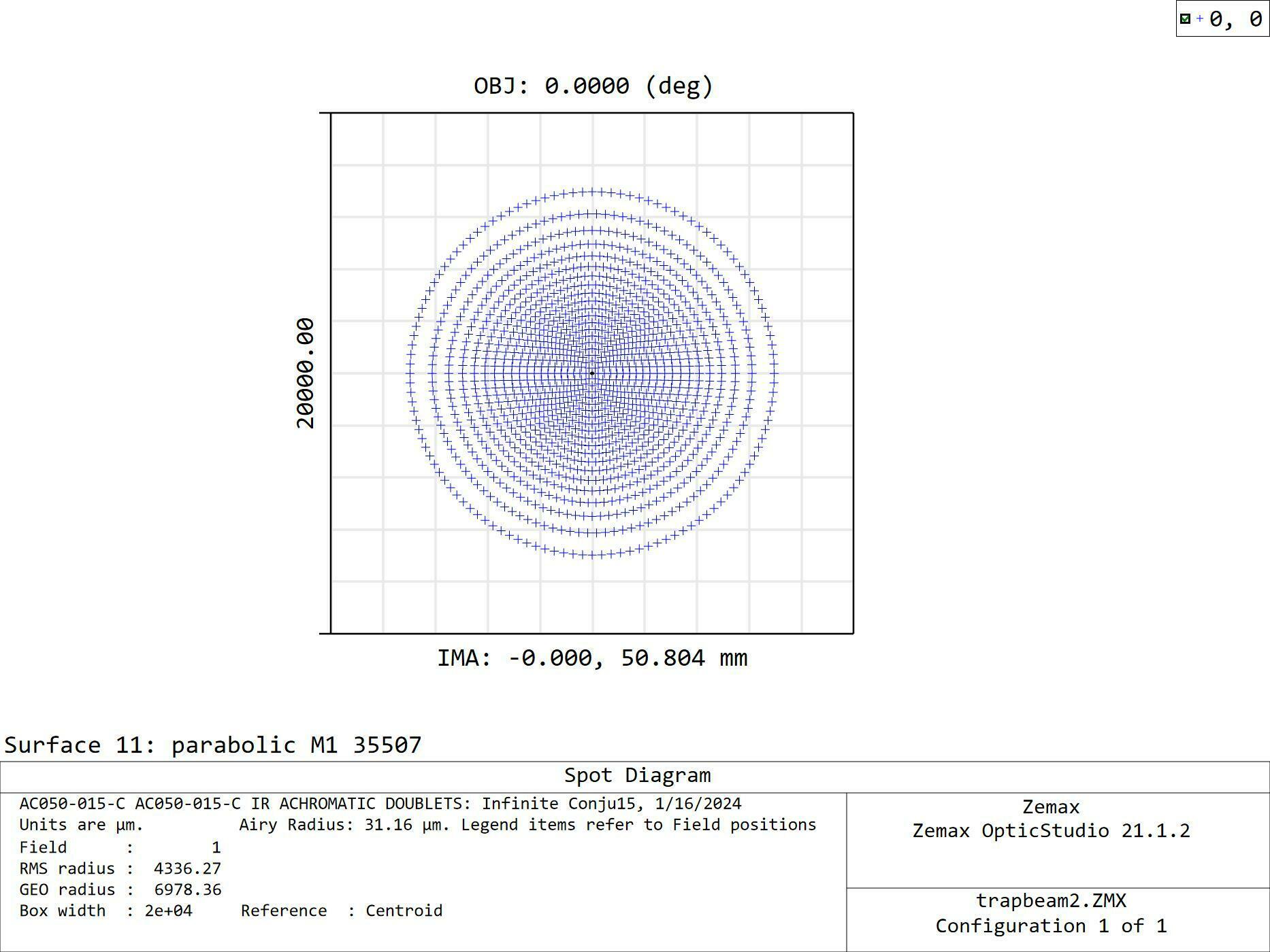
My goal at the moment is to set up a model based on existing optics. I’ve copied various surfaces provided by manufacturers and put them together in the zmx file attached. The layout looks like this:

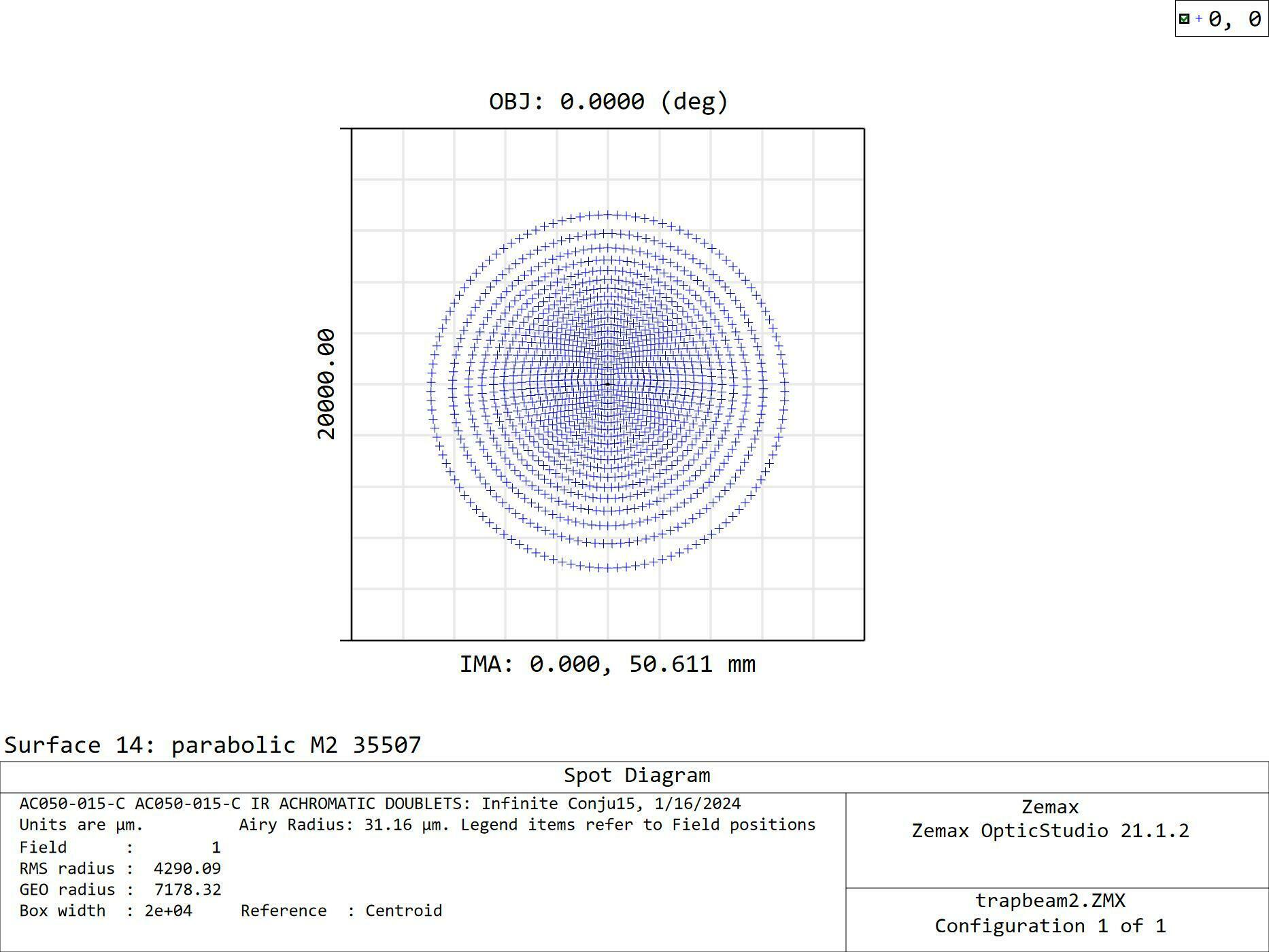
In Zemax, I first collimated the input beam by running ‘quick adjust’ twice. As you can see, the spot diagram on the first parabolic mirror (M1) looks reasonable. Then I did another ‘quick adjust’ to optimize the space between M1 and the second parabolic mirror M2. The beam ended up looking skewed on M2 and IMA. and I expect at least a axially symmetric profile.


I think My problem has to do with the parabolic mirrors, probably with how I optimized the geometry. While I’m not sure if the beam would focus perfectly to one point as in the original model from Edmund, I think the output beam should look more symmetric at least. What should I optimize to achieve more symmetry?
Also, in the model provided by Edmund optics, both surface thickness of the mirror and tilt about Y in the coordinate break that follows are solved for. When I incorporated them into mine, I made all of them (on M1 and M2) fixed. When I left them as variables in M2, the optimized values turned out quite different. I feel that at least ‘thickness’ should not change because it’s a physical property, yes?
I’m very new to Zemax. Any suggestions are appreciated.

