Hi,
I am trying to develop a GRIN lens model for my optical design. However, the profile of the beam output is not correct. I would like to learn how I can fix it.
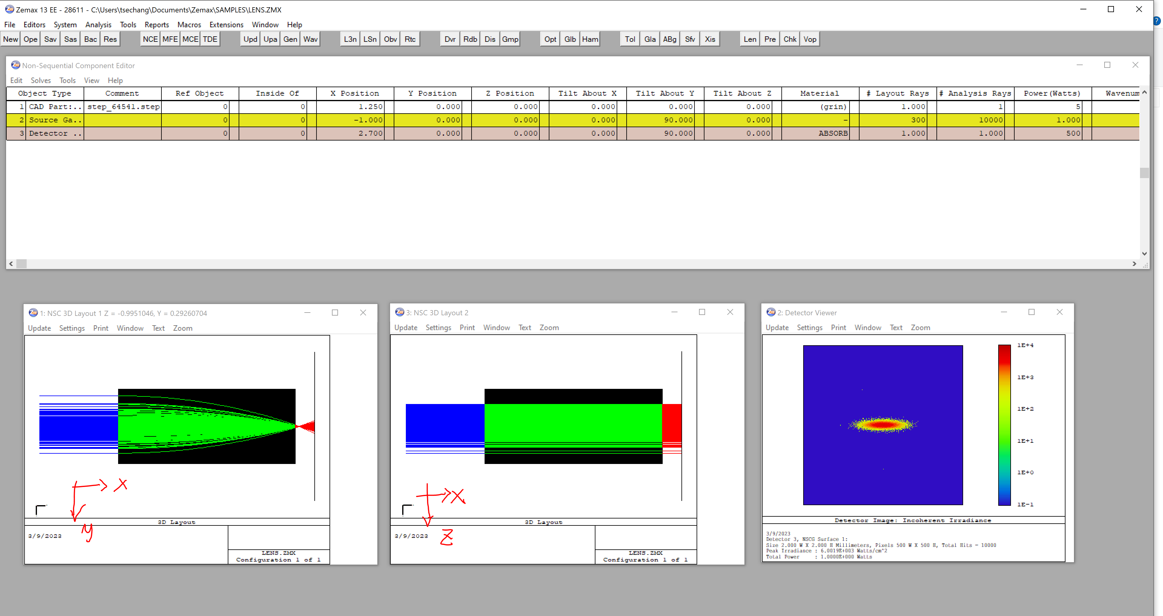
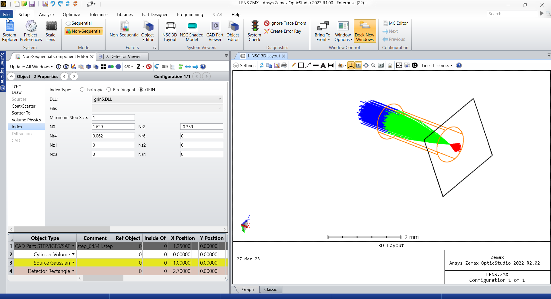
Below is a screenshot of the result I have from Zemax 13. As we can see, the beam only focuses on one axis (y-axis). The width in the z-axis reminds the same. I tried to run the simulation using OpticStudio 22.3, but the result reminds the same.

I followed this thread to start my work.
The GRIN lens I use is from Edmund #64-541.
(https://www.edmundoptics.com/p/10mm-dia-810nm-dwl-00mm-wd-nir-coated-grin-lens/19253/)
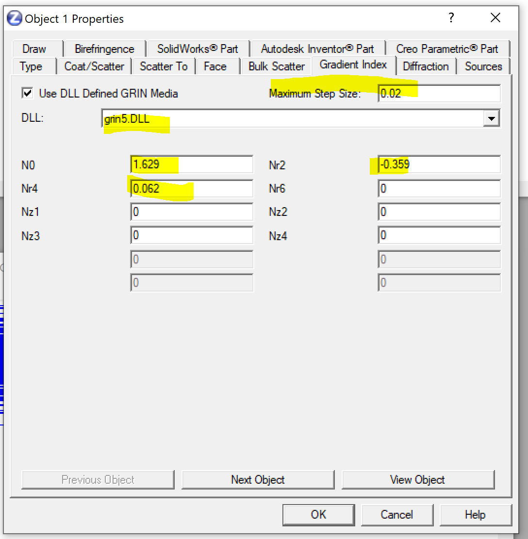
I imported the .step file downloaded from the website and assigned the index based on what I got from the sequential mode.


I feel this issue comes from the .step file. I tried to draw a solid cylinder with 1 mm in diameter and 2.38 mm in length (the same as the dimension of the GRIN lens), but it did not work… Maybe I should not draw a solid cylinder directly. Or it was actually caused by other issues.
The .ZAR file is attached for your reference. I appreciate your help in advance.
Thanks,
Tse-Shao


