

Hey Zemax team,
Sadly my license for OS does not include the new ‘draw entrance and exit pupils’ feature, but I saw a posting on LinkedIn that leads me to think it’s not correct. https://www.linkedin.com/posts/ir-ekim-yildirim-bb9481161_did-you-know-that-zemax-2024-r1-can-draw-activity-7179440511521292288-86_4?utm_source=share&utm_medium=member_desktop
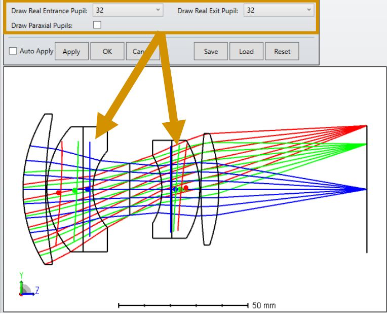
I’m assuming that the red pupils are the off-axis pupil (and so sees the red rays). The pupils appear to me to be:
- tilting the wrong way
- not centered on the chief ray of the field point
I can’t play with the feature to satisfy myself. Could someone post this layout (its the double Gauss sample file) with ‘Draw Marginal and Chief Rays’ selected please?
- Mark
