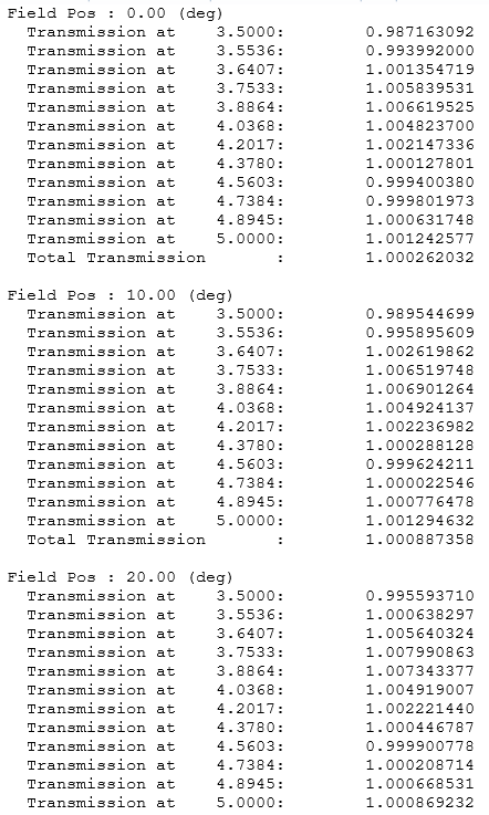
I have a MWIR coating on a germanium substrate (with internal transmittance set to 1.0) and I’m getting double-sided transmission greater than 1.0. How is this possible? This result disagrees with Code V, Filmstar and Essential Macleod. Even if I vary the layer thicknesses by 3%, transmission still can exceed 1.0 at angles of incidence less than or equal to 20 degrees.
Best answer by MichaelH
Hi James,
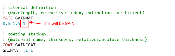
The first thing that comes to mind is if you’re using a MATE/COAT values for a “real” coating, then the extinction coefficient for the MATE material has to be negative to be “absorbing”; if the third value in the MATE section is positive, you will experience gain. Based on the stack of different materials, this could be slightly less than 1 for some wavelengths/angles and slightly more than 1 for other wavelengths/angles:
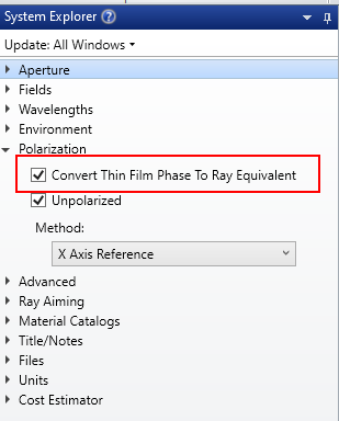
Next, I would ensure the Convert Thin Film Phase to Ray Equivalent is checked; the method OpticStudio uses for intensity is different than some of those other software you named (especially Macleod) and this conversion will attempt to make the definitions compatible.
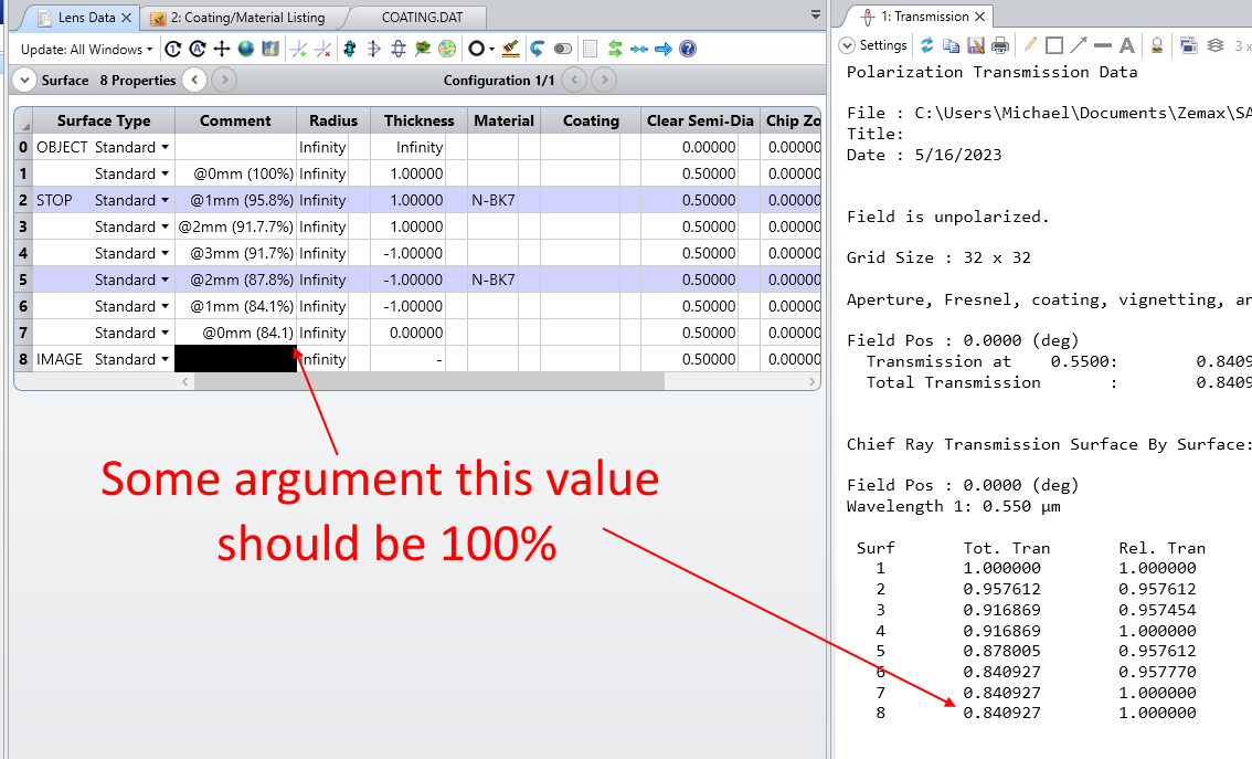
Lastly, do you have any virtual propagation/Coordinate Breaks in your system? There were attempts a few years ago to make the LDE more realistic for virtual propagation but the simple scenario I can remember doesn’t appear to have been implemented. Namely, if you travel “forward” through 1mm of N-BK7, you should experience loss and then you travel “backwards” through -1mm of N-BK7, some in the community were making the argument you should experience gain. There was a release (at least a Beta) in 2020 or 2021 that implemented this but I believe this functionality has been rolled back (the recommended method is to define a new material and new coating which applies the gain rather than having OpticStudio “guess” what the intended behavior is). If this is still present in your version of OpticStudio and you’re using virtual thicknesses, add a 0 thickness dummy surface around your materials to get the desired beavhior:
Finally, if none of these work, can you upload your file/coating? The Polarization Ray Trace as a lot of information in it (Ken basically dumped the entire debugging process of the polarization ray trace into a report for users) and that can really help pinpoint if this is a calculation error or the intended behavior (as OpticStudio understands it to be).
The first thing that comes to mind is if you’re using a MATE/COAT values for a “real” coating, then the extinction coefficient for the MATE material has to be negative to be “absorbing”; if the third value in the MATE section is positive, you will experience gain. Based on the stack of different materials, this could be slightly less than 1 for some wavelengths/angles and slightly more than 1 for other wavelengths/angles:
Next, I would ensure the Convert Thin Film Phase to Ray Equivalent is checked; the method OpticStudio uses for intensity is different than some of those other software you named (especially Macleod) and this conversion will attempt to make the definitions compatible.
Lastly, do you have any virtual propagation/Coordinate Breaks in your system? There were attempts a few years ago to make the LDE more realistic for virtual propagation but the simple scenario I can remember doesn’t appear to have been implemented. Namely, if you travel “forward” through 1mm of N-BK7, you should experience loss and then you travel “backwards” through -1mm of N-BK7, some in the community were making the argument you should experience gain. There was a release (at least a Beta) in 2020 or 2021 that implemented this but I believe this functionality has been rolled back (the recommended method is to define a new material and new coating which applies the gain rather than having OpticStudio “guess” what the intended behavior is). If this is still present in your version of OpticStudio and you’re using virtual thicknesses, add a 0 thickness dummy surface around your materials to get the desired beavhior:
Finally, if none of these work, can you upload your file/coating? The Polarization Ray Trace as a lot of information in it (Ken basically dumped the entire debugging process of the polarization ray trace into a report for users) and that can really help pinpoint if this is a calculation error or the intended behavior (as OpticStudio understands it to be).
Wow, that is quite a slap in the face. Coating engineers have been supplying me with coefficients that are positive in value, perhaps because Filmstar and Essential Macleod load in positive values but the codes makes them negative? Checking with them--the coating engineers--on that.
Anyway, I believe an update to the coatings section of the manual is warranted. The only example of extinction coefficient use in there is for aluminum (which we all know doesn’t transmit). The example is followed by the statement: “Note the extinction coefficient is negative using this convention for typical absorbing materials.” There is a statement preceding that aluminum definition, namely “K is written as a negative value in the coatings” but that should probably say “Extinction coefficients should all be negative unless you want gain coatings.”
Thanks very much for taking me to school regarding my bizarre results, Michael. Much obliged!