Solved

Multimode fiber bundle


Dear All,


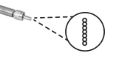
I would like to simulate beam divergence from the linear fibre bundle, which includes 7 small circular fibres (200um core diameter, NA 0.22). 

I have tried the Source Ellipse, with the given core diameter, by changing the values for Gx and Gy I see that the beam charges from collimating to diverging. But there I am not sure how to calculate the values for the Gx and Gy.

How to set the NA in Source Ellipse? Which type of source can I choose from NSQ, that I can set the core diameter and NA? 


Thanks in advance.


Astghik

icon

Best answer by David 7 May 2021, 01:10

View original

5 replies

Userlevel 6
Badge +4

Hi Astghik,


One issue with modeling fiber output is that the angular distribution of the output can depend on the stimulus at the fiber input. However, I have used several methods for approximating fiber output:


1) The Source Ellipse in the Source Distance mode. Here the source aperture is filled with rays such that all the rays appear to emanate from a point. We can calculate the source distance as the semidiameter / Tan[halfAngle]. This is reasonable in the far field, but in the near field or for imaging applications the fact that the fiber output appears as a point source is a strong disadvantage.


2) The Source Ellipse with a Gaussian specification. The Intensity as a function of direction cosines is given by I = I0 Exp[-Gx l^2 - Gy m^2]. If Gx = Gy then the distribution is radially symmetric since l^2+m^2 = (1 - n^2). We can, for example, calculate Gx = Gy = G such than at angle theta the intensity falls to 1/E^2 from G (l^2+m^2) = 2, where l^2+m^2 = (1-n^2) and n^2 = Cos^2[theta].


3) We can also use Source Radial, with intensity vs. angle entries to produce an arbitrary radially symmetric distribution.


I like #2 best.


I've attached a ZAR file with examples of these three methods for a 200um fiber with an NA .22, 12.7 degree half angle output.


Kind regards,


David
Dear David,


Thank you very much for your explanation and the attached files. They helped me a lot to design what I wanted.


Best regards,


Astghik

Hi Astghik,


One issue with modeling fiber output is that the angular distribution of the output can depend on the stimulus at the fiber input. However, I have used several methods for approximating fiber output:


1) The Source Ellipse in the Source Distance mode. Here the source aperture is filled with rays such that all the rays appear to emanate from a point. We can calculate the source distance as the semidiameter / Tan[halfAngle]. This is reasonable in the far field, but in the near field or for imaging applications the fact that the fiber output appears as a point source is a strong disadvantage.


2) The Source Ellipse with a Gaussian specification. The Intensity as a function of direction cosines is given by I = I0 Exp[-Gx l^2 - Gy m^2]. If Gx = Gy then the distribution is radially symmetric since l^2+m^2 = (1 - n^2). We can, for example, calculate Gx = Gy = G such than at angle theta the intensity falls to 1/E^2 from G (l^2+m^2) = 2, where l^2+m^2 = (1-n^2) and n^2 = Cos^2[theta].


3) We can also use Source Radial, with intensity vs. angle entries to produce an arbitrary radially symmetric distribution.


I like #2 best.


I've attached a ZAR file with examples of these three methods for a 200um fiber with an NA .22, 12.7 degree half angle output.


Kind regards,


David


5

Dear David,

Thank you very much for your explanation and the attached files. After my test, also #2 best. Do you have more information to help introduce the derivation of#2 formula?

Userlevel 6
Badge +4

Let’s take it a step at a time.

First, a few words about the direction cosines: l, m, n. If we think about the direction as a vector in 3-space, (l, m, n) are the cosines of the included angles between our direction vector and the three Cartesian coordinate axes: (x, y, z) respectively. Since we are only concerned with direction, we can consider the magnitude of the vector to be 1. Then the direction cosines are also the projections of our unit magnitude direction vector on the coordinate axes. This means that the direction cosines (l,m,n) are in fact the cartesian coordinates of the unit vector representing the given direction. So the square magnitude of the vector is l^2 + m^2 + n^2 which we have said is 1. So is l^2 + m^2 + n^2 = 1 is an identity.  Notice that while we describe our direction in terms of (l, m, n), the identity can be used to express any of the three components in terms of the other two. So we really need only two components to define a direction. We could think of the two components as a polar angle with respect to the z coordinate axis and an azimuthal angle.

The formula OpticStudio uses for intensity is

   I = I0 Exp[-Gx l^2 - Gy m^2], where Gx and Gy are different parameters.

The formula does not include the direction cosine with respect to the z-axis, which is n. However, we could use the identity given earlier to express this in terms of n and either l or m. So this is not necessarily radially symmetric about z. For that, the intensity needs to be a function of n alone, since that is the cosine of the angle with respect to z.

But look at what happens when Gx = Gy. Then let Gx = Gy = G and rewrite the expression for intensity:

   I = I0 Exp[-G l^2 - G m^2] = I0 Exp[-G (l^2 + m^2)]

We rewrite the identity is l^2 + m^2 + n^2 = 1 as l^2 + m^2 = 1 - n^2 and substitute:

   I = I0 Exp[-G (1-n^2)]

Now the intensity is only a function of the angle subtended between the given direction and the z axis.

We can also see that the intensity falls to 1/e^2 when G (1-n^2) = 2, where n^2 = Cos^2[theta] with theta being the angle between the given direction and the z axis.

Also note that since Sin^2 + Cos^2 =1:

   1 – n^2 = 1 – Cos^2 = Sin^2

So the intensity falls to 1/e^2 when G Sin^2[theta] = 2. For small theta, Sin(theta) is approximately theta so the intensity falls to 1/e^2 when G theta^2 = 2. ( theta in radians )


Dear David,

Thank you very much for your explanation.

Your answer suddenly made me enlightened! #2 is very effective in simulating the laser output of multimode fiber. I've been looking for it for a long time.

Reply