Hi,


I am optimizing for three configurations of fields with different entrance pupil location . Let's say for example:


Fields:


config 1


x = 0 , y = 0


x = 0 , y = 5


x = 0 , y = -5


config 2


x = 4 , y = 0


x = 4 , y = 5


x = 4 , y = -5


config 3


x = -4, y = 0


x = -4 , y = 5


x = -4, y = -5


How zemax calculate analsys plots ike mtf map, grid distortion, image simulation for multiple configurations? When choosing configuration in these plot what exactly happen?(see below)
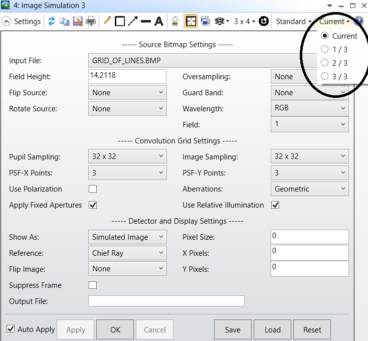


Do I need to make new file with all these fields in only one configuration to get meaningful results?


Best regards,


Nadav


Hi Nadav,


When you choose one configuration on any analysis, OpticStudio will use only this configuration (with its corresponding data) for all calculations and graphics. Therefore, you can not simulate the formation of images for the three configurations at the same time. 


However, you can optimize across configurations. To select which (or all) configurations to optimize, open the Optimization Wizard from the Merit Function Editor. Depending on the selection, OpticStudio will build the appropriate merit function for one or all of the available configurations.


Best,


Berta


Hi Berta,


Thanks for the quick answer.


So after optimizing the configurations, in order to get meaningful  image/mtf map, I need to make a new file with all these fields in only one configuration?


Becasue the fields do not enter from the same pupil...


Best,


Nadav


Hi Nadav,


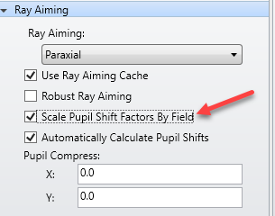
Just to be clear, is there a specific reason why you're defining all of these fields in separate configurations? If all the fields are not entering from the same Entrance Pupil, it sounds like you might want to enable Ray Aiming. In fact, there is a checkbox setting that you can define which will allow each field point to have it's own pupil shift for systems which are highly tilted/decentered:


If you're unfamiliar with Ray Aiming, we have a couple of handy Knowledgebase articles that you can take a closer look at:


This would then allow the STOP surface to be properly filled with rays, meaning the resulting analyses would be more accurate, and so I don't think there would be a need to define your field points in three separate configurations. Of course, if I'm missing anything in your needs here, let us know!


~ Angel


Hi angel,


I change it to one configuration now and it's work better, by usuing the vignetting factors.


Thanks for the help,


Nadav


Reply