
Hello,
I would like to modelize different benches, some on the top and some on the bottom.
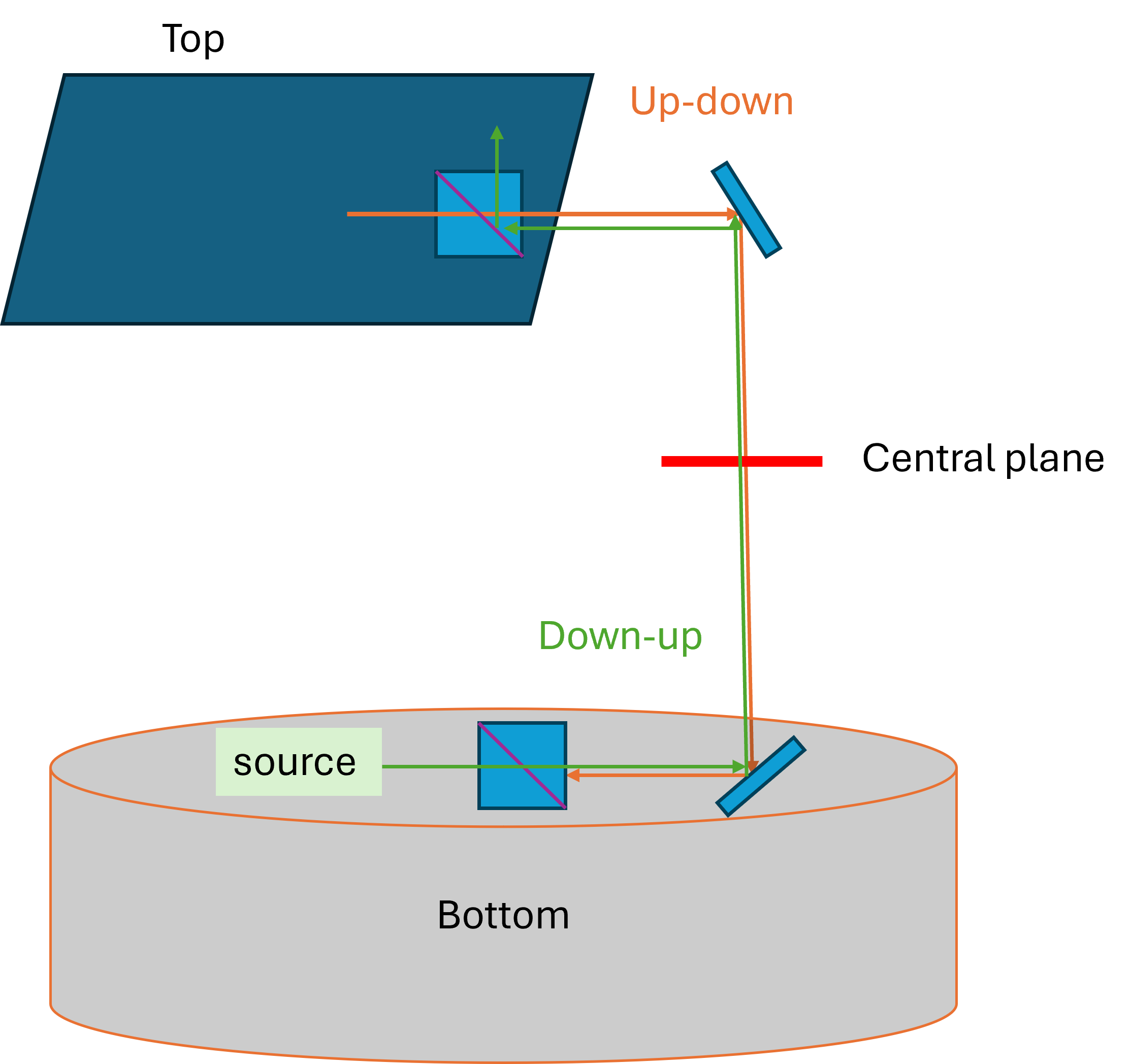
I use multi-configuration editor to do so. I have a beam coming from the top bench going to the bottom bench (top-down), with a central plane where the beams of the other benches will go at the end.
I chose that my central plane is the global coordinate reference surface.
I have a beam from the bottom bench, with a source, which has a path and going through the same optics (PBS etc.) of the way (top-down) but it is going through them in the “opposite” direction to go on the top bench (down-up), through the central plane.
To model that, I just add all the surfaces from this down-up direction in another configuration (“configuration B”), before the central plane, and ignore them in the other configurations (“configuration A”), only the central plane is common to all configurations. I then model again the optics which the beam from the bottom is going through, until the central plane. I ignore for this configuration B all the surfaces after the central plane. For mirrors, steerings, I put the right rotation.
That does not work well and this configuration B is floating from the top to the bottom…
Any advice for my modelization ? Is it possible ?
Thank you a lot for your help.

