Solved

Model Fresnel reflection in non sequential mode

  • 25 January 2022
  • 5 replies
  • 468 views

Hi, 

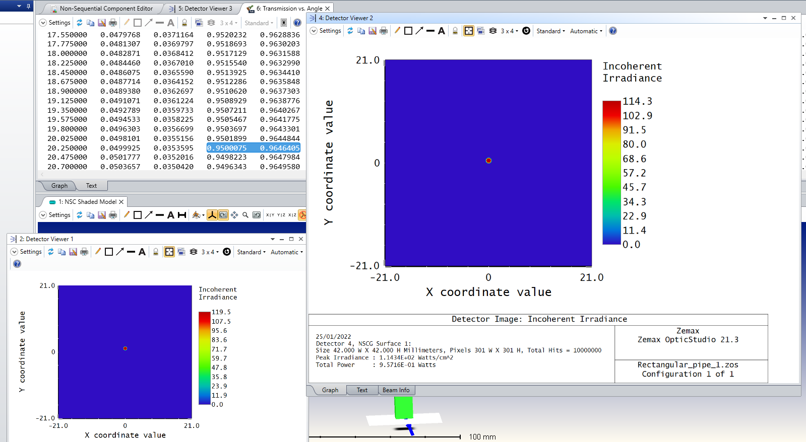
I am wondering how to include Fresnel reflection in a simple non sequential model : I have a pipe from which I am entering with light from the side. In order to verify if Optic Studio already models reflection at the air-glass interface, I have placed a detector before and after the interface. With 1 W source power I get the same on the second detector, both for normal incident light and light tilted at an angle. This makes me think reflection is not taken into consideration here. 

On the other hand, if I check the transmission vs angle plot I can see transmission is computed correctly:

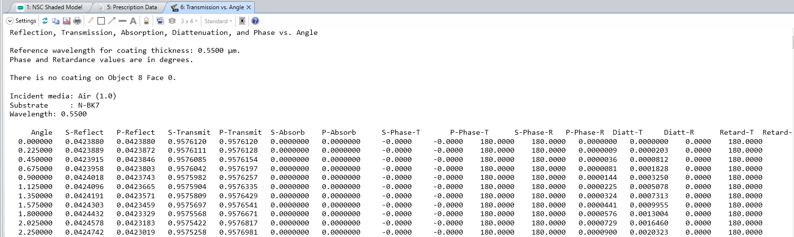
Why is detector 2 then not giving a total power of 0.96 W at 0 incident angle? How can I model it in a way I have this information on my detector? 

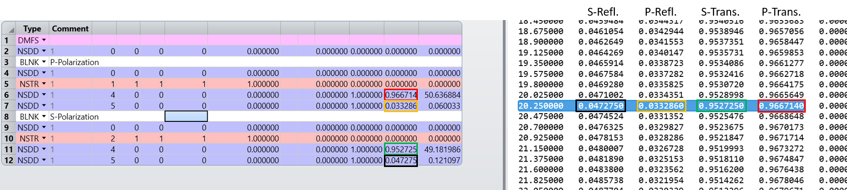
I have tried to tock the reflection option for the front face of the object, but this results in a mirror like behavior, which is not right either: 

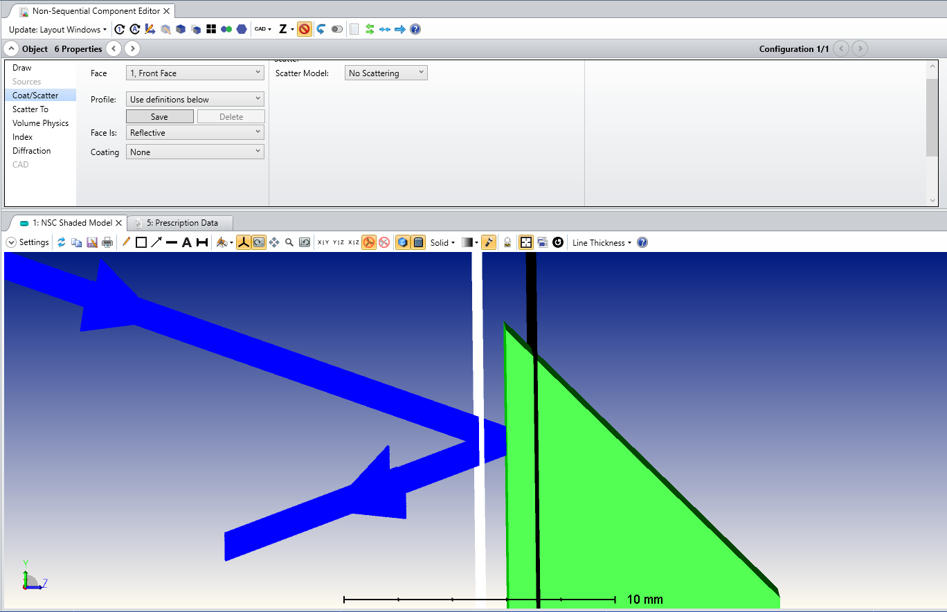
Thank you to whoever will answer me!

Giulia.

icon

Best answer by Sven.Stöttinger 25 January 2022, 16:07

View original

5 replies

Userlevel 2
Badge

Hi Giulia,

did you check the “Use Polarization” box in the ray trace control? Without it Zemax does not take Fresnel reflections into consideration.


Best regards,

Sven

Dear Sven,

thank you for your reply. Now I did and the value changed, thank you. 

One more question though. In this case, the power detected on the second detector should be the arithmetic mean value between s and p polarization values, right? 

at 20.25 deg incident angle for example I get 0.9500075 and 0.9646405.

The mean should be 0.9573 and not 0.95716 as displayed in the detector. (Here I am assuming it because incident power is 1 W). Is there something I am not considering, maybe?

And more, I guess reflection is considered at each interface and each light bounce.

Thanks again,

take care,

Giulia.

I guess 0.014% is not a big deal, probably is due to slightly different calculations…


Thank you!

Userlevel 2
Badge

Hi Giulia,

I did a quick “sanity”-test to look at the transmitted and reflected flux for two linear polarized sources in a setup similar to yours. You can set up linear polarized sources via the polarization tab:


If you look at the results for the linear polarized sources, you’ll see that it matches the calculated values from the table, and therefore OpticStudio simulates the reflection and transmission properly.

My guess is that it has something to do with how the random polarization is achieved. I’m not sure how OpticStudio generates its “random polarization”, but it might be just the case that the outgoing rays are not 100% equally distributed with regards to the p- and s-polarization direction which could explain why the result for the unpolarized rays do not correspond perfectly to the arithmetic mean of the s- and p-polarization based values.


Best regards,

Sven


Dear Sven,

thank you very much for your time and feedback! I really appreciate! 

best,

Giulia.

Reply