I am able to define the distances between the objects in Non sequential mode.
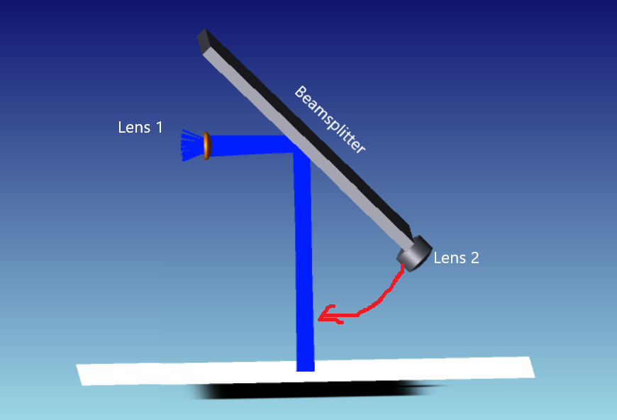
But when the object is rotated say for example a beam splitter is tilted, how can I define other objects by considering beam splitter as a reference ? In the below layout, Beam splitter is the reference for lens 2, I want to position the lens 2 in the arrow marked space.
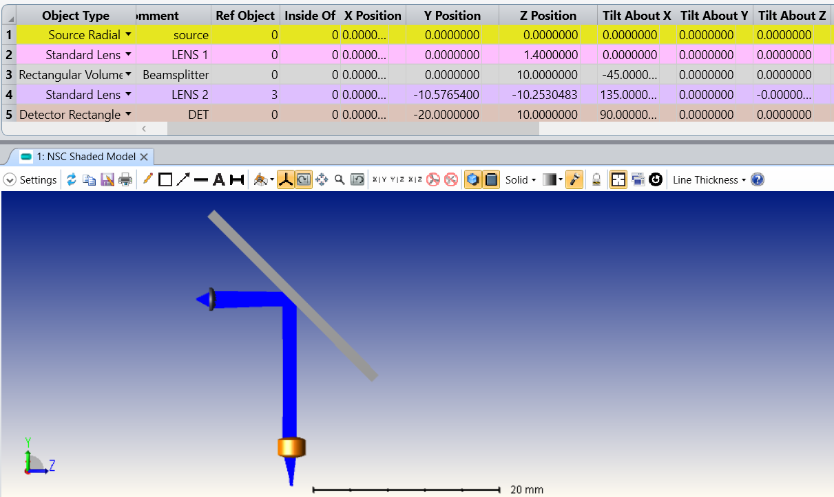
And also please help me to understand the z axis position of beam splitter, here in the image it is 10mm where the lens 2 located. Why not it considers the center of beam splitter as z position. Help me to understand the z position here.
Rays are scattered/Reflected at lens 1, is it un avoided one. Help me on how to avoid this. For reference I have attached the zar.file. Kindly check and suggest any possible way to perfectly define distances with ref to tilted objects.
Thank you
Ebi
Best answer by mojtaba.falahati
Hi Ebi,
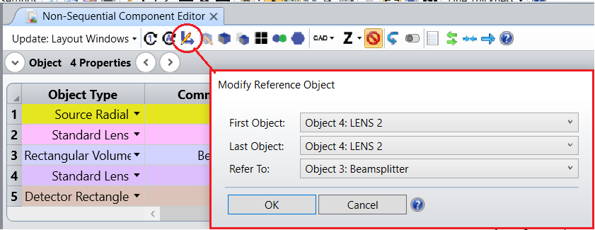
1- The Object placement depends on the nature of the position data you have. If you have the object position data in the Global system you can directly define the Position and Tilt for the object in NCE. Then, you can use the Modify Reference Object tool to find the relative position with respect to a reference object as described here: How to use the Modify Reference Object tool – Knowledgebase (zemax.com)
If you have the relative position and orientation of an object with respect to another object, you simply set the Ref. Object in the NCE and populate the position/tilt parameters. Then, the coordinates of the object are referenced to the location and rotation of the specified object.
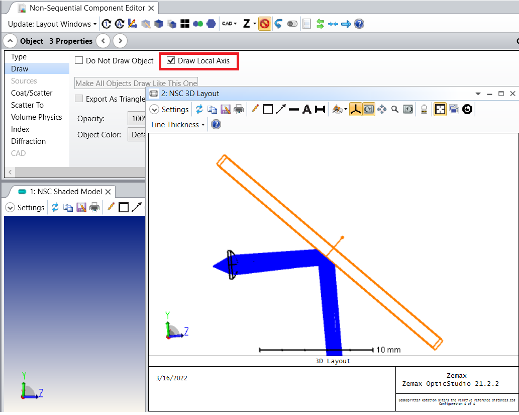
2- Each object’s position is defined by 6 parameters: the x, y, and z coordinates, and the rotation about the x, y, and z axes. OpticStudio first decenters in x, y, and z (decenters are orthogonal so the order does not matter). Then OpticStudio tilts about the local x axis (which rotates the y and z axes to new orientations), then tilts about the new y axis (which rotates the x and z axes), then finally tilts about the new z axis. You can display the local axis in the 3D Layout by checking on the Draw Local Axis in the Object Properties.
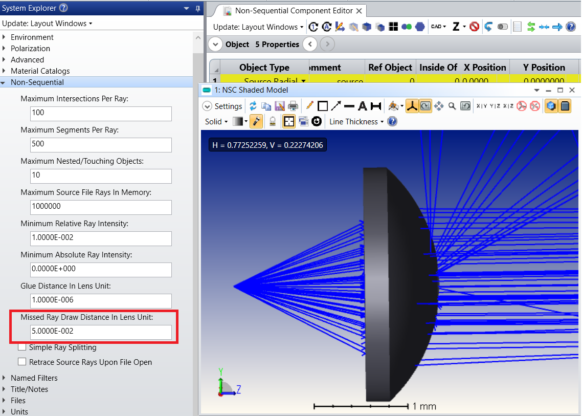
3- You have defined some coating on the Lens 1 surfaces which results in ray splitting. If you modify the surface coating (to be only transmitting) you no longer see ray splitting. You may also uncheck the Split NSC Rays in Ray Trace window if you are not interested in Ray splitting in the entire system (which I do not think is the case as you have a beam splitter). If your concern is just about the model display you can set an arbitrary number for Missed Ray Draw Distance In Lens Unit in the System Explorer to make the missed rays look shorter in the Shaded model.
1- The Object placement depends on the nature of the position data you have. If you have the object position data in the Global system you can directly define the Position and Tilt for the object in NCE. Then, you can use the Modify Reference Object tool to find the relative position with respect to a reference object as described here: How to use the Modify Reference Object tool – Knowledgebase (zemax.com)
If you have the relative position and orientation of an object with respect to another object, you simply set the Ref. Object in the NCE and populate the position/tilt parameters. Then, the coordinates of the object are referenced to the location and rotation of the specified object.
2- Each object’s position is defined by 6 parameters: the x, y, and z coordinates, and the rotation about the x, y, and z axes. OpticStudio first decenters in x, y, and z (decenters are orthogonal so the order does not matter). Then OpticStudio tilts about the local x axis (which rotates the y and z axes to new orientations), then tilts about the new y axis (which rotates the x and z axes), then finally tilts about the new z axis. You can display the local axis in the 3D Layout by checking on the Draw Local Axis in the Object Properties.
3- You have defined some coating on the Lens 1 surfaces which results in ray splitting. If you modify the surface coating (to be only transmitting) you no longer see ray splitting. You may also uncheck the Split NSC Rays in Ray Trace window if you are not interested in Ray splitting in the entire system (which I do not think is the case as you have a beam splitter). If your concern is just about the model display you can set an arbitrary number for Missed Ray Draw Distance In Lens Unit in the System Explorer to make the missed rays look shorter in the Shaded model.
Thank you so much for the help and support. Regarding the answer for 1st question, Can you briefly explain , how the exact y and z positions and tilt about x values are found ?