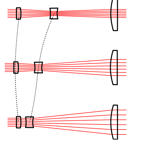
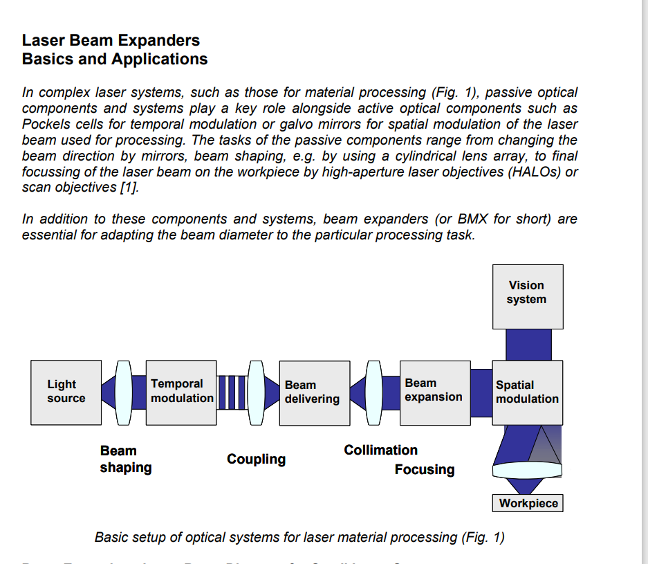
I would like to work out the magnification of my zoom beam expander, which I am building for the first time. The system I have in mind should look like this
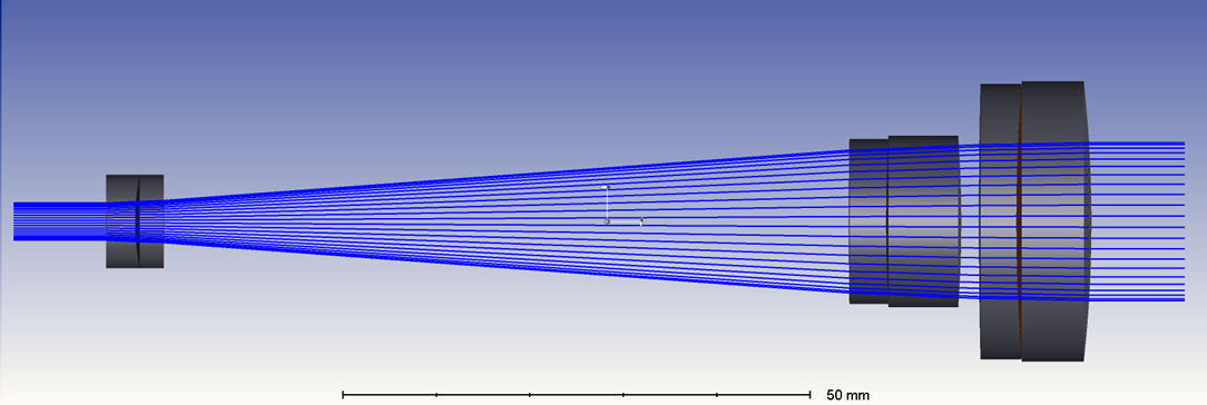
or like from Zemax templet
What are the focal length relations between those 3 lenses? Which type of lenses are most suitable for such a design?
I will appropriate any tips.
Thank you,
Regards,
Marzanna
Best answer by David
Hi Marzanna,
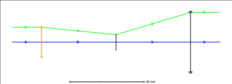
Matrix methods for paraxial optics is good at this kind of problem. If you are not familiar with it, a ray is described at each point in its travel through an optical system by a vector giving its height above the optical axis and its angle with respect to the axis. Optical components -- including lenses, mirrors, and transfers through space -- are represented by matrices, which can be multiplied in series to describe a transfer function for the system.
In your design, the input ray can be given as having height 1 and 0 angle. For the output ray to be collimated its angle is zero and it has height equal to the magnification. The transfer function acting on the input therefor produces two equations. The system has 5 degrees of freedom: 3 focal lengths and two air spaces. This means that a few extra constraints are needed. I use these to pick reasonable values for some focal lengths. This can be an iterative process.
I used Mathematica for this work. I am sure Matlab would also work. I have attached a PDF of the Mathematica notebook. And also the notebook itself inside a zip, in case it’s useful. They may be difficult to read if you’re not familiar with Mathematica. But if you look into matrix optics, I’m sure you’ll get the idea.
The result of my choosing some values and analyzing the zoom looks like this. The lengths carry the same dimensions as the focal lengths.
Thank you for the great work you put into your answer. I understand the ABCD matrix and the concept of calculating the beam magnification based on the height of the ray input vs ray output. Although, I don’t quite understand your plot (sorry). What would you advise on approaching this task using commercial lenses? I know the beam radius on the input and its maximum magnification on the output, but for now, it looks like going through many lens combinations.
Also, in the pictures attached to my first post, in order to achieve the zoom, in the first picture only the middle (bi-concave lens) changes its position while in the second example ( from Zemax templet) the second and the last lens are moving. I assume two options are true but which one is better?
In my graph, the two air spaces are the air thicknesses in the design. Air Space 1 is before the central negative element; Air Space 2 is after the negative element. With the three focal lengths fixed, these are the airspaces required to produce a collimated output with the magnification indicated on the x-axis.
Regarding the fixed track length design, I do not believe it will work with the three focal lengths fixed. With that set of constraints, the only remaining variable is the position of the central element, given by a single air thickness. There are still two conditions to satisfy: 1) the output must be collimated (equivalent to an RAID = 0 operand in the merit function) and; 2) a specific magnification (equivalent to an REAY operand). So the system is over constrained.
Doing computer algebra with the matrix methods, I found that when the three focal lengths and the track length were fixed and the constraint of collimation was imposed, there were two solutions for magnification. One was smaller than 1, the other greater than 1. But any solution for a different magnification was not collimated.
You can also see this in a simple paraxial design in OpticStudio. The merit function attempts to impose both conditions and cannot meet both, except at the two magnifications. There are two magnifications at which this can be done: 2 and .2. (Attached as a zar.)
It is likely possible to achieve a fixed track length by splitting the central element into two elements which are allowed to move independently. This would produce the equivalent of a variable focal length central element.
Regarding commercial lenses:
Most of my work with beam expanders has been with fixed magnification Galilean designs. There, for a small input beam, the first element needs to be of very short focal length and therefor small diameter. You may find the same with the Keplerian architecture. Lens choices are limited, but fortunately a number of companies make suitable lenses specifically for such work. A good place to start looking is ThorLabs. (Many of their specialty lenses do not appear in the OpticStudio lens catalog.) Another advantage is that a number of these lenses are aspheric designs optimized for collimation.
I recommend working in OpticStudio with simple lenses, even paraxial lenses, to get a good idea of the focal lengths required, and then looking for similar elements available off-the-shelf. Then you may need to compromise design specifications, like magnification range and track length, to make use of the parts you find
I looked at the paper you referenced. To avoid confusion, I edited my Mathematica notebook to match their variable names. When I solve for the air spaces d1 and d2, I get this:
This matches the equations (5) and (6) given in the paper.
However, it does not match the equations or numbers you give above.