When modelling a non-sequential system depending on whether I tick the 'Use Polarisation' in ray trace, I get 90 or 62 percent output. In the display I cannot see any significant diversion of rays (yes I am ticking and unticking the use polarisation button in the settings of NSC model) . How can I see where the 28% energy is being lost.
It is UV light with mostly fused silica components. The source is a IESNA file with angular variation.
Best answer by David
Without polarization Fresnel reflections and absorption are not modeled. The losses are from rays that fail to hit the detector. With polarization Fresnel reflections contribute to the losses.
You can get an itemized list of the power in the various paths by using Path Analysis under the analyze tab. You need to save path or ray data during the ray trace first. Path Analysis will also generate filters that can be used in a filter string to visualize the various paths on a layout.
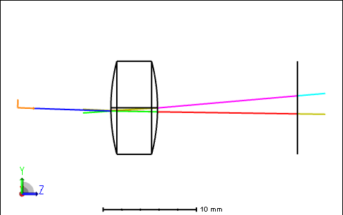
In non-sequential you can of course determine the overall trannsmission by tracing rays to a detector with splitting on in the ray trace control. This tells you the total loss, but not where it happens. You can visualize the back reflections by turning on splitting in the layout:
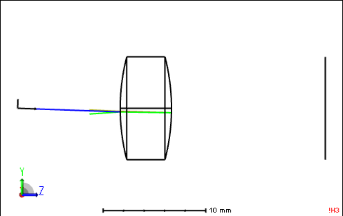
You can save data to a ray database during the trace and use a filter string to show only the branches that don't hit the detector:
Neither of these quantify the result.
You could use the Ray Database viewer to look at intensities for a single ray traced through the system, but the interpretaton is a bit annoying.
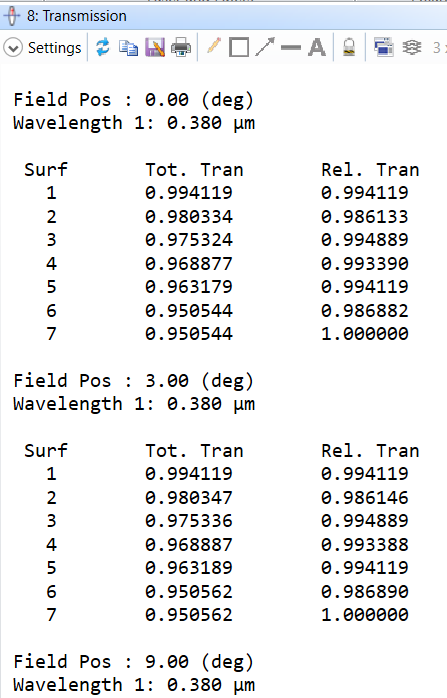
The most quantitative way that comes to mind is to use the Polarization / Transmission analysis in sequential mode. This shows the relative transmission for each surface for the chief ray of each field. If you start work in sequential, it's convenient to design coatings at that point to reduce Fresnel losses. (The example is from a different file.)
There may be a better way to do this in non-sequential, but I can't think of one. (I also have a hard time seeing exactly what capabilities exist for the various OS levels, since nothing is grayed out in my version.