Solved

Light Propagation Through Optical Fiber

  • 19 January 2022
  • 14 replies
  • 428 views

Userlevel 1

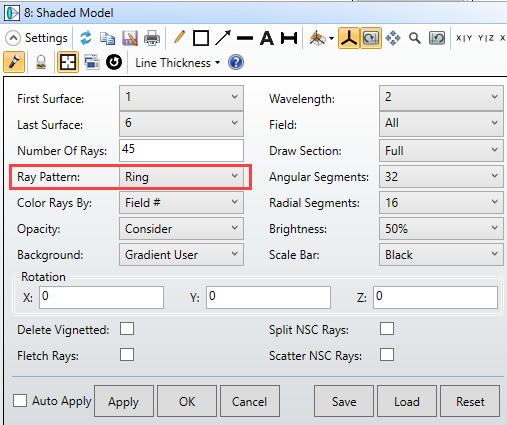
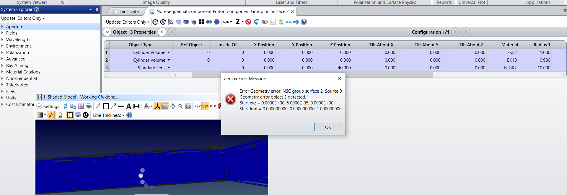
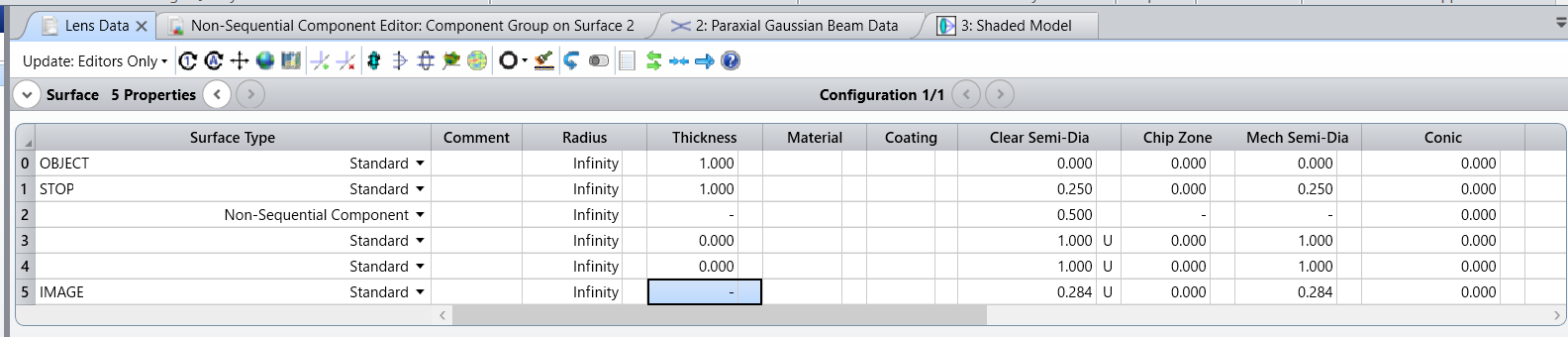
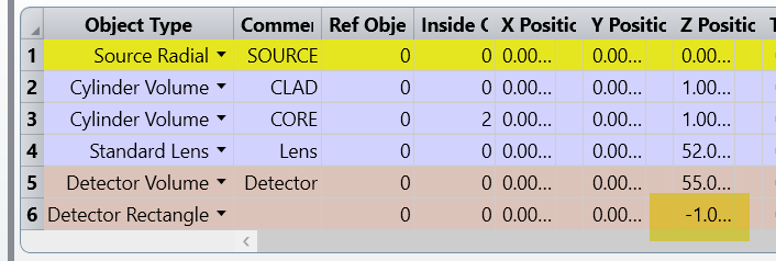
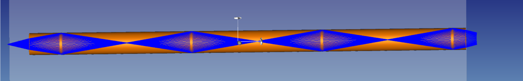
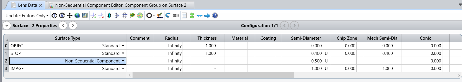
 I have tried to model the propagation of light through the fiber, but my model doesn't looks it undergoes TIR. Can anybody please help me to identify what parameters should I check and alter ? Expecting your guidance on this for my good understanding. (For your reference i have attached the LDE of Seq & NS and the parameters) Kindly let me know if any more parameters needed

Core Nd=1.49 ; Clad Nd=1.43

EPD = 0.5 (Syst Expl)

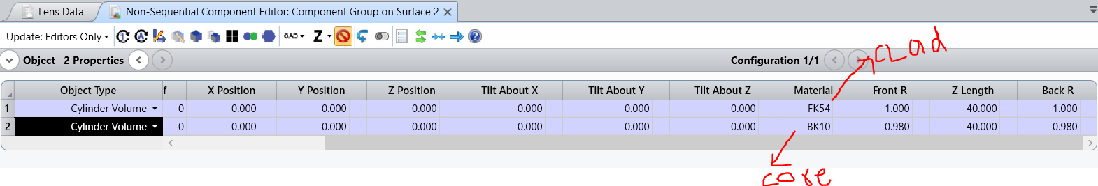
Core dia = 0.98 micron

Clad dia = 1 micron

SEQ LDE
NS LDE

Actual Expectation: 


icon

Best answer by Jeff.Wilde 20 January 2022, 04:18

View original

14 replies

Userlevel 7
Badge +3

I assume the first graphic you show is from a Shaded Model window.  It appears that you have a ring of rays, all of which do in fact experience TIR and therefore refocus inside the fiber.  Note that the default ray pattern for a Shaded Model view is a “Ring.” 


If you want to see a collection of rays over a range of input angles, then select a different option such as “Grid.” 

Userlevel 1

Thanks a lot Jeff Sir, 

I got it. And i am trying to couple the lens at the end of my fiber to alter its divergence in order to analyze the light beam profile before and after passing through fiber and then finally after passing through the lens. So I put my lens after the fiber, but it shows error in Obj 3 geometry. I have tried but it looks some guidance required for me.

where i have done mistake sir ? Seeking your reply


Userlevel 7
Badge +3

Where is the Exit Port of your NSC group located (this is surface 2 in your sequential lens data editor)?  Be sure the exit port is defined so that your lens stays inside the NSC group, otherwise you will get an error.  See “How to use NSC with Ports” in the help documentation, specifically the section that discusses “The Exit Port.” 

Userlevel 1
Yes surface2

I unable to change any parameters under radius column also, I have read the Exit port documentation. Unable to find out where the problem is, Expecting some more suggestions. If possible let me know sir.

Userlevel 7
Badge +3

What are the coordinates of your exit port (x,y,z) location?  Also, is your lens touching the fiber or is there an air gap between them? 

Here is a Knowledgebase article that could be helpful: How to locate geometry errors: Part I

Userlevel 1

since It seems all in good alignment, I haven't defined XYZ, it is 0,0,0. In that above picture my lens didn't touch the fiber. but I want my lens to touch the fiber. So when I make the z position of lens to touch the fiber, it shows error. 

Userlevel 6
Badge +2

Hi Ebi

Would you be able to attach your file? It would be easier to fix it. 

Userlevel 1

Thanks Ms.Sandrine, I have attached the file, My expectation : I want the the lens to converge the ray from fiber , But my lens not at all functioning. My aim is to study the beam profile after the ray passes every object, like before the entry port, after ray passed through fiber and finally  in the focal plane. Is it possible ? or can i do this in NSC mode alone. I would be happy if this problem got solved.

Userlevel 1

Hi Jeff sir, This is Regarding the ray patterns in 3D layout. In grid pattern the input angle was considered ryt, You mean angles we usually give in the FIELD ? Can you please tell me the uses of different ray patterns. Like when to use what ? 


Userlevel 6
Badge +2

Hi Ebi 

Can you attach a zar file? (File….save as...zar). The file you attached is a session file that conly contains the analysis windows that are open in your session. Thank you!

Userlevel 1

Hi Ms. Sandrine, Thanks for the help. I have attached my current ZAR File. I am doing LED beam propagation through fiber followed by a lens immediately, and I want to measure the divergence angle and power after every object in the NSCE.  I have encountered a few errors in doing this. I would like to know where the parameter fault is. This may seem simple but your valuable suggestion will be very helpful for my better understanding.

It was made in Pure NSC.

  • And also when split rays were checked  in layout properties, the rays are reflected back towards my source, Why, can you please briefly explain.
  • While modelling, few rays are not properly refracting at the lens in NSC Shaded but obeys in NSC 3D, How can I eradicate these? 
  • How to measure the divergence and power of the beam after fiber and after lens?
  • If  any other parameter errors found, Kindly let me know that too. 

Awaiting for your response 

Thanks and regards

Ebi


Userlevel 6
Badge +2

Hi Ebi

  • Rays coming back to the source are probably reflected by the front and back face of the fiber because of Fresnel reflections. You can filter rays with filter strings, use the Ray Database viewer or the path analysis to visualize the path taken by those rays.
    For example I have added a detector before the source.
    I can use the Path Analysis to see the rays that hit that detector. 

    This will also help you to assess the quantity of rays that go towards the source.
    We have some good articles that explain how to use these tools like:
    Identifying specific rays using filter strings
    Introduction to stray light analysis - Part 2
    Stray light analysis for Head-up-Display - Part 2

  • For your 2nd question, could you show the rays on a screenshot? 

  • For the divergence and power, you can measure it on a detector and also use a merit function to retrieve some values. Again have a look at our articles. 
    Detectors used in illumination design

I would recommend reading our free tutorial https://www.zemax.com/blogs/free-tutorials/illumination-systems-fundamentals to give you some good references. We also have some online courses for a fee.

Userlevel 1

Hi Ms.Sandrine,

Thank you so much. I have done it. Regarding 2nd question the problem got solved, its my mistake of wrong input parameter. I will go through the references you gave. One more clarification.


Rays may behave non sequentially ? Will this affect the performance of the system if the intensity of the particular ray is high ?


Userlevel 6
Badge +2

Hi Ebi

In non-sequential, if you tick Split Rays and Use polarization, you will get a better understanding of the whole system performance. For example path number 3 represents all the rays that follow the sequence. These rays represent 0.25% of the total flux.

Reply