Question

lens magnifier effect simulation

  • 2 November 2023
  • 4 replies
  • 141 views

Hi,

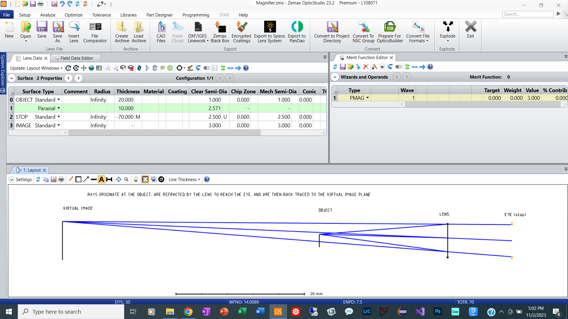
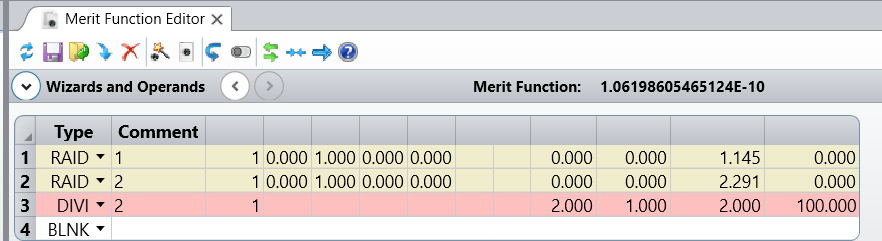
I have little experience with zemax, but I’m working on something for which I guess zemax can help. A positive lens acts as a magnifier when the object is placed within its focal lenght distance. In this case no real image is generated, rather a virtual one. In systems like watchmakers loupe, the user places the eye near the lens in order to see a magnified rendering of the object. I’m interested in evaluating how the magnification perceived by the eye varies as the object position varies or when the object position is fixed and the focal length of the magnifier varies. What would be the best model setting up to make such a study? Thank you for any help you can provide. 


4 replies

Userlevel 6
Badge +4

Hi Piero,

This can be done by tracing rays from a real object height through the lens to the eye. The eye acts as the system aperture stop, just as it does in reality. The lens has bent the rays so that they arrive at the eye as though diverging from a magnified object at a more distant location. The rays striking the eye are back traced using a negative distance to a virtual image plane. 

In the attached file, a single off axis field point is used for clarity. The lens is a paraxial lens, which could of course be replace with a practical lens. The distance to the virtual image is set with a marginal ray height solve to force the image plane to the focus. A PMAG (paraxial magnification) operand in the merit function is used to measure the magnification.


Hi David, 

thank you very much for your replay and the file. It looks a very good approach to me. Thanks again.

Kind regards

Piero

Userlevel 6
Badge +4

You are very welcome, Piero.

One thing I might add to this. The magnification reported by PMAG is probably not the magnification we usually associate with a hand magnifier. It compares the height of the virtual image to the height of the real object. But the virtual image is also farther away, and it’s not really “real.”  The angular magnification is probably more useful.

The attached file (magnifier 2) uses ray angles reported by RAID operands to calculate the ration between the angle of the chief ray at the eye to the angle at the lens, which would be the angle at the eye if the eye were located at the lens. This ratio is the angular magnification seen by the observer and can be used as a merit function target.


Dear David,

Thank you very much for your input. In your latest file, the STOP surface has a M solve. This makes  the location of the virtual image, with respect to the STOP, changing, depending on the focal of the paraxial lens. What I see is that the ratio of the chief ray angle at the STOP to the one at the lens  does not correspond to the result for the angular  magnification expected by Physics. According to the Physics of the lens, the magnification is given by M=(250/f)+1, where 250mm is the distance of the near point of the eye (For instance a lens with 25mm focal length should provide a magnification of 11). The near point is the distance of the object at which the eye forms the largest sharp image on the retina.  To my comprehension of the magnifier physics, when you put a lens in front of the eye, and very close to it, the eye accommodation and the object position are eventually arranged by the user in such a way that the image is always produced at a distance corresponding to the near point. So magnification is given by the angular ratio of the chief ray angle to the eye when the lens is in place (and the virtual mage is at the near point), divided by the chief ray angle when the object is observed by the naked eye at the near point.  Therefore, in my file, the distance between the STOP and the virtual image plane is fixed at 250mm regardless the focal length of the paraxial lens. What must be physically changed is the thickness of the object (the distance between the object and the paraxial lens) in such a way that the image at 250mm is the sharpest possible. So I constructed the merit function like this:

1) Calculate the angle of the chief ray with the lens in place (RAID operand).

2) Calculate the angle subtended by the object at the near point for the naked eye (CONST).

4) Imposing the object thickness to be less then focal length of the paraxial lens (PLMT).

5) Targeting the RSCH to zero, in order to get the sharpest image. Only parameter with weight 1.

6) Dividing value of point 1 by value of point 2 in order to get the corresponding angular magnification.


With such a settings, when I change the focal length of the paraxial lens, the object thickness is updated by the Optimize command in order to get a sharp image at the near point; and the updated magnification value corresponds very well to the value predicted by the magnifier formula. This makes me quite comfortable for my study.

Kind regards

Piero

Reply