I would like to simulate a laser diode in Non-sequential mode. I am attaching here the datasheet of the laser diode I would like to simulate.
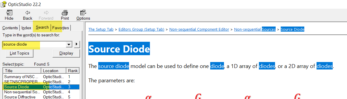
On Zemax: I set as Object type → Source Diode
After having set the wavelength, the Layout Rays, and the power I am getting stuck on this information:
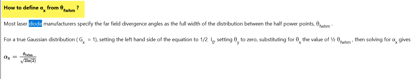
X/Y-Divergence
X/Y SuperGauss
Number X’/Y’
Delta X/Y
Can someone help me having a look to the file attached (datasheet diode laser) to fill the abovementioned parameters?
Many thanks in advance
Gianluca
Page 1 / 1
Hi Gianluca
I had a quick look at the datasheet.
For the angular distribution, it gives the half angles:
So check the help files. It shows how to convert half angles into αx. I would use the typical value to start of with.
The datasheet doesn’t really give any distribution so you could go for gaussian.
For the spatial distribution, I am not too sure about the size of the emitted area based on the datasheet. There is a mention of an emission point. Maybe you could use a point for the definition.
Otherwise a more simple model to start is the Source Two Angle.
The “Source Diode” asks for the parameters both for the angular divergence and for the spatial source size. I would think that these two sets of parameters are mutually dependent: The angular divergence is that of the diffraction pattern from the source size.
Does anyone have thoughts on this?
@Joel.Seligson:
The Source Diode is a ray-based source, not wave-optics based, so the user needs to provide both spatial and angular properties. Depending on what you are doing, the near-field spatial or the far-field angular profile might be the primary feature of interest, but it’s probably good practice to make them reasonably self-consistent with one another from a diffraction perspective.
In contrast, the Source Diffractive requires the near-field spatial shape, and then computes the angular distribution of rays using a diffraction analysis. However, the spatial shapes are limited to hard-edge user-defined apertures (*.uda files).