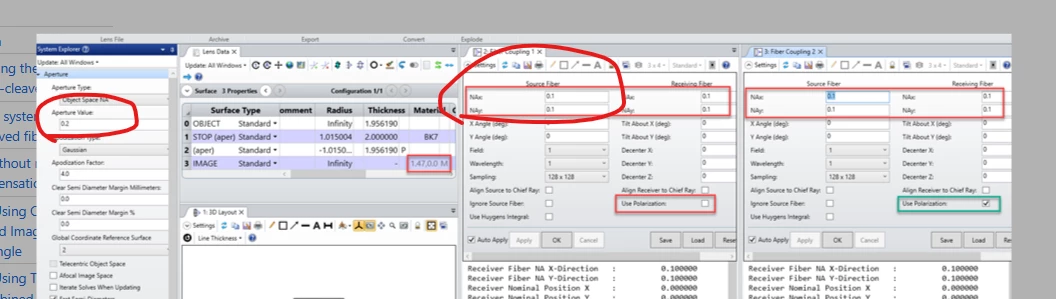
As far as I know, the fiber coupling efficiency does not use the system NA to calculate, but you need to input in the its own
And I am just wondering, why the two NA do not match? say, both NA 0.2 or NA 0.1
the tutorial shows a setup like
obj- lens- image
simulates source fiber - lens - receiver fiber
so shall the light source NA = source fiber?
it will be appreciated if you point out my misunderstanding
thank you
Yang
Best answer by Jeff.Wilde
The system NA sets the maximum angle for source rays used in any ray tracing analysis. In the single-mode coupling efficiency analysis, the Source NA defines the 1/e^2 intensity angle for the fiber (or waveguide). In general, you want the system NA to be 1.5X to 2X larger than the fiber NA so that the tails of the Gaussian beam from the fiber are not clipped by the system aperture in any meaningful way. To better understand this effect, you can keep the fiber NA at 0.1 and vary the system aperture NA from say 0.05 to 0.2, and you will see the impact of fiber beam clipping by the system aperture.
The system NA sets the maximum angle for source rays used in any ray tracing analysis. In the single-mode coupling efficiency analysis, the Source NA defines the 1/e^2 intensity angle for the fiber (or waveguide). In general, you want the system NA to be 1.5X to 2X larger than the fiber NA so that the tails of the Gaussian beam from the fiber are not clipped by the system aperture in any meaningful way. To better understand this effect, you can keep the fiber NA at 0.1 and vary the system aperture NA from say 0.05 to 0.2, and you will see the impact of fiber beam clipping by the system aperture.
The system NA sets the maximum angle for source rays used in any ray tracing analysis. In the single-mode coupling efficiency analysis, the Source NA defines the 1/e^2 intensity angle for the fiber (or waveguide). In general, you want the system NA to be 1.5X to 2X larger than the fiber NA so that the tails of the Gaussian beam from the fiber are not clipped by the system aperture in any meaningful way. To better understand this effect, you can keep the fiber NA at 0.1 and vary the system aperture NA from say 0.05 to 0.2, and you will see the impact of fiber beam clipping by the system aperture.