Solved

Intro to Lens Design ZEMAX - Transmission Sphere Design Question

  • 3 May 2023
  • 6 replies
  • 388 views

Userlevel 1

Hello ZEMAX community, 

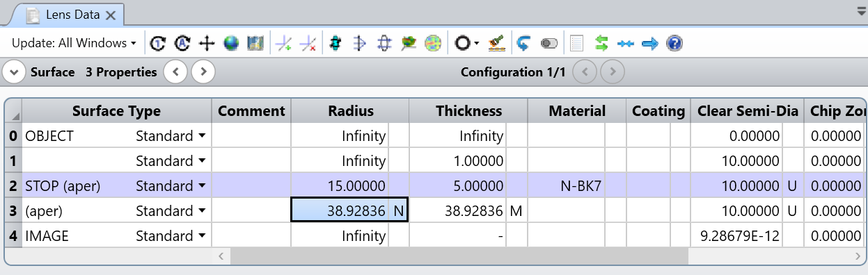
I am currently practicing the Lens Splitting based on the <Introduction to Lens Design in ZEMAX> Chapter 9. The problem is to design a transmission sphere as described in below. I got the spot diagram to be close to the Airy disk, but not exactly smaller. My struggle is that I could not understand/use notes (d).

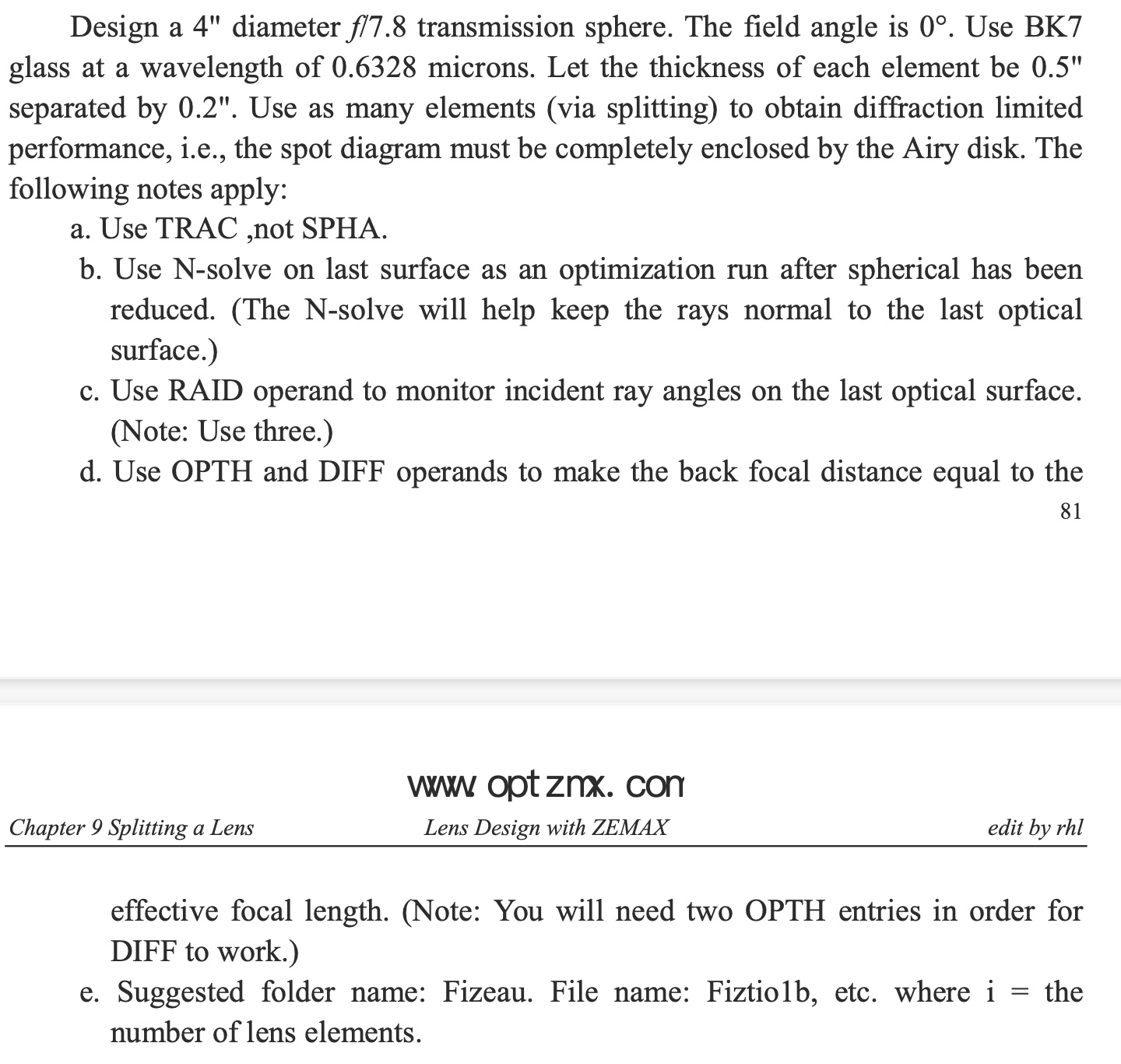
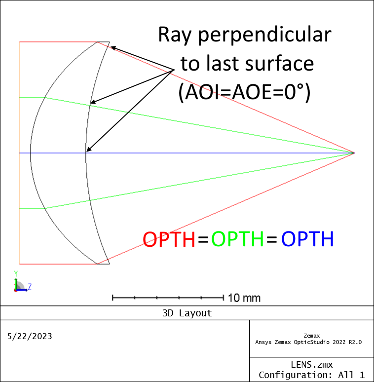
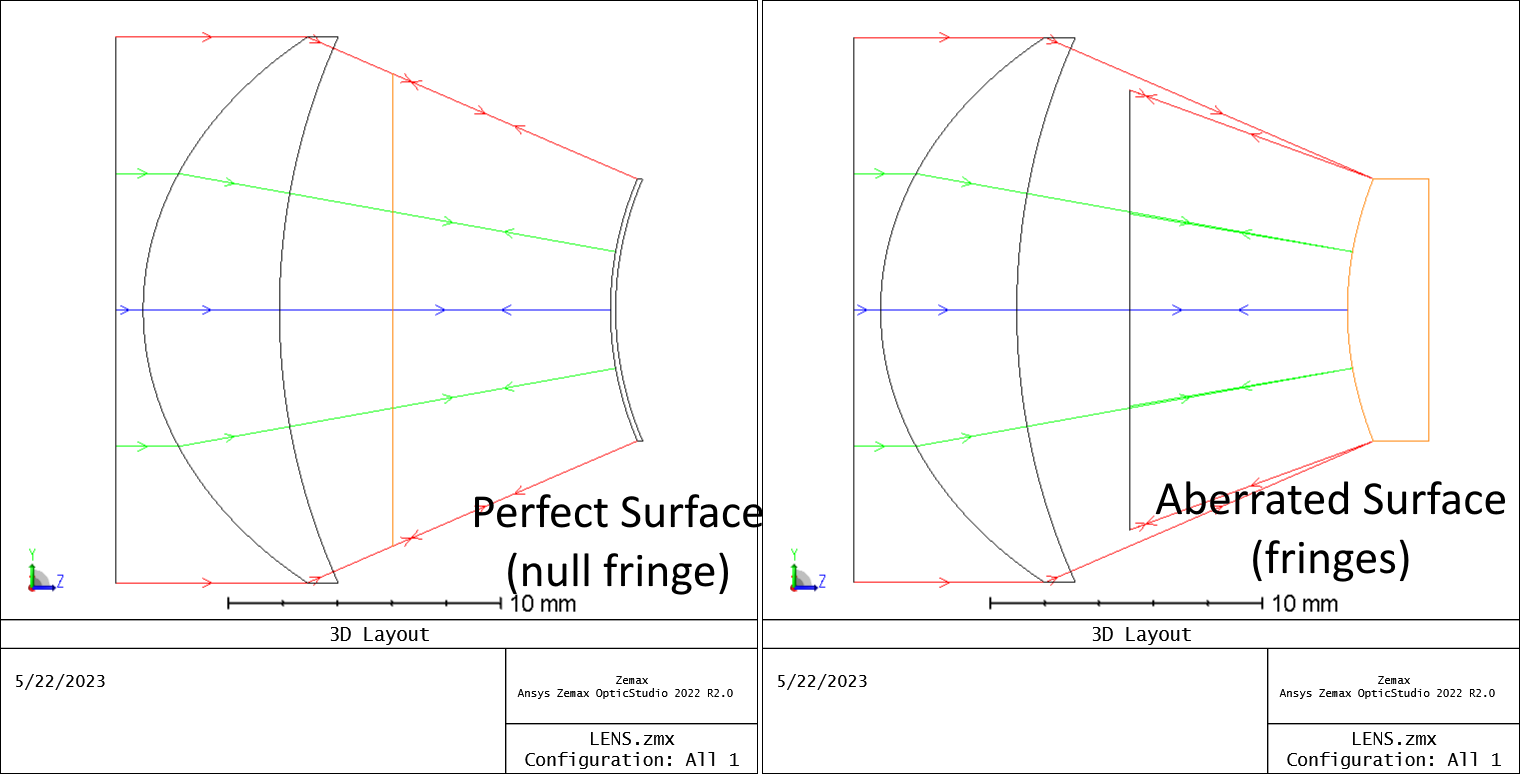
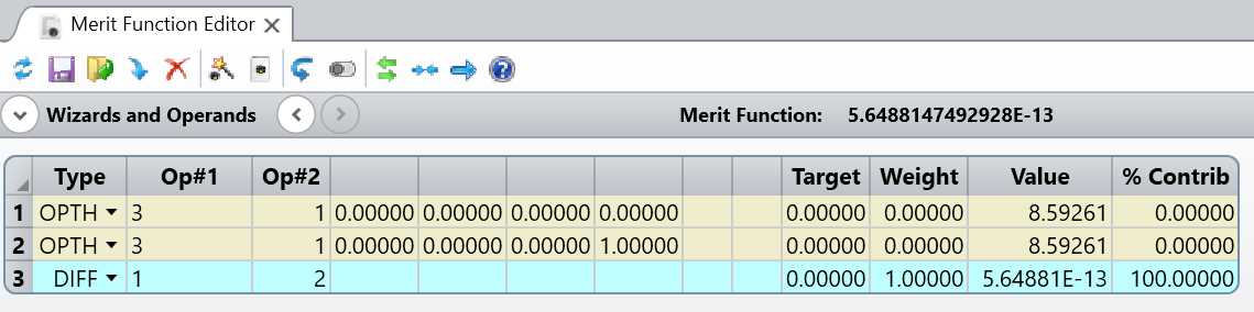
My question is in the notes (d) provided. It says the condition for the transmission sphere is BFL = EFFL and use the Operands OPTH and DIFF. Here, I understand that the OPTH calculates the optical path based on a selected surface. But I could not think how to use two OPTHs to make it work.

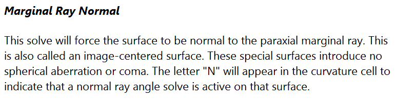
Alternatively, I searched that the critical design condition for the last surface is that its radius of curvature needs to be equal to the BFL. To me, to equate the radius of the last surface (6th) = BFL (TTHI operand), and use DIFF to optimize the difference is zero makes more sense. 

Can anyone please comment on the question or verify if my thoughts are right?

Thanks in advance!


Regards,
Yadong


icon

Best answer by MichaelH 22 May 2023, 18:38

View original

6 replies

Userlevel 7
Badge +2

Hi Yadong,


I’m not sure either how the author intended to use OPTH (and I’m curious to know if someone knows), but there are often several ways to go about the same problem in OpticStudio.

One thing I’d say is that there’s an operand EFFL that gives you exactly that, the effective focal length. Therefore, if you want the BFL to equate the EFFL, I’d just take DIFF of EFFL and TTHI of the penultimate surface (probably surface 6 in your example), and target it to zero.

Take care,


David


Userlevel 6
Badge +2

Hi Yadong,

Since this is my second time attempting to write an answer (Zemax did not save my first attempt and discarded everything I wrote), I’ll be more brief and probably skip over some points.  Not sure what the author is talking about with EFL = BFL (this can simply be achieve by placing the Stop at the last surface but this doesn’t make the system a Transmission Sphere), but the key concept for a Transmission Sphere is the last surface is the reference surface and the wavefront leaving this reference surface should be perfectly spherical (for monochromatic, on-axis).  This means that the AOI = AOE = 0°.  This condition, along with a well corrected optical system before the last surface, will cause all the rays across all the pupil zones to have the same OPTH (each ray’s OPL will equal the radius of curvature):

This is needed to create a null fringe for a perfect test surface or aberrated fringes for an aberrated test surface.  You can see from the fletched arrows on the left that the rays going to and reflecting off the test surface follow the exact same path, thus having 0 OPD across the wavefront:

I believe the author is trying to say your MFE should look like:

However, I would recommend to not use MFE operands when you can use solves in the LDE.  Since the AOI = AOE = 0°, you can use the Marginal Ray Normal on the last surface and use a Marginal Ray Height on the last thickness:


Userlevel 7
Badge +3

I agree with the previous comments.  I would only add that use of the N-solve is already called out in part (b) of the problem, and (d) is a separate constraint.  Forcing the EFL to equal the BFL simply places the 2nd principal plane of the lens at the last lens surface.  Why do this?  It makes the diameter of the beam leaving the transmission sphere equal to the input collimated beam diameter (or entrance pupil diameter, EPD).  Using the OPTH operand to make this happen wouldn’t necessarily be the first thing that comes to mind, but doing so seems very simple.  Just calculate the OPL of the chief ray to the image plane (OPL1) and to the last lens surface (OPL2), then take the difference, and force this difference in the merit function to equal the target EFL (or OPL1 - OPL2 => EFL).  We know the target EFL because the problem prescribed the EPD (4”) and the image-space f/# (f/7.8), and the EFL is just the product of the two (EFL = 4” x 7.8 = 31.2”).

Regards,

Jeff

PS: Since this is a homework problem, the goal may not be to ask the student to proceed along the most straightforward path, but to think about a less-obvious alternative approach...

Userlevel 6
Badge +2

Thanks Jeff for the clarification about the BFL = EFL.  In my original post (which was lost and thus my new post about a Chrome Extension for auto-saving responses), I mentioned that making the BFL (a mechanical distance) and the EFL (an optical distance) would require placing the Rear Principal Plane (the plane of unit magnification) at the last vertex.  This could be achieved by using the CARD operand, Data 5 (this operand was probably implemented after the author created the homework problem) and does really teach why you want the EFL = BFL like you mentioned (i.e., a 4” input beam to the TS is also a 4” output beam at the last surface).  I didn’t even think of this to put 2 and 2 together.

As for the N-solve, I didn’t even realize the author was referring to the Marginal Ray Normal; it makes sense when I take a step back and look at the actual LDE.

Once again, thanks for making the complex simple.  

Userlevel 7
Badge +3

Thanks Michael for the positive feedback.  This is a fun little homework problem!

Userlevel 1

Hello @David.Nguyen,

Thanks for the reply. I actually used your method eventually for this problem. The reason that I post this question is just checking whether the community has any users who know what the author was initially asking or the clue he tried to give. Thank you.


Hi @MichaelH!

Thanks for 2 attempts in writing down the detailed explanation. I had similar glitch before be ZEMAX always had an emergency backup file saved when I restart the ZEMAX...I do not need to start from scratch again…

I haven’t got time to go through your method yet (in office now). I will try it later at home.


Thanks again! and hope all of you have a great day!

Reply