Dear community,
there are already several questions about that topic and also there are useful support here:
https://support.zemax.com/hc/en-us/articles/1500005486701-How-to-simulate-high-resolution-images
However, I am still having some doubts about the following questions.
Let consider that I am in the condition in which I have a 1:1 magnification lens, and I am setting the Field Type as Object height at 5 mm as “Max Field Y” and I have set the distribution as “Uniform Y Fields”. So I am in this condition:
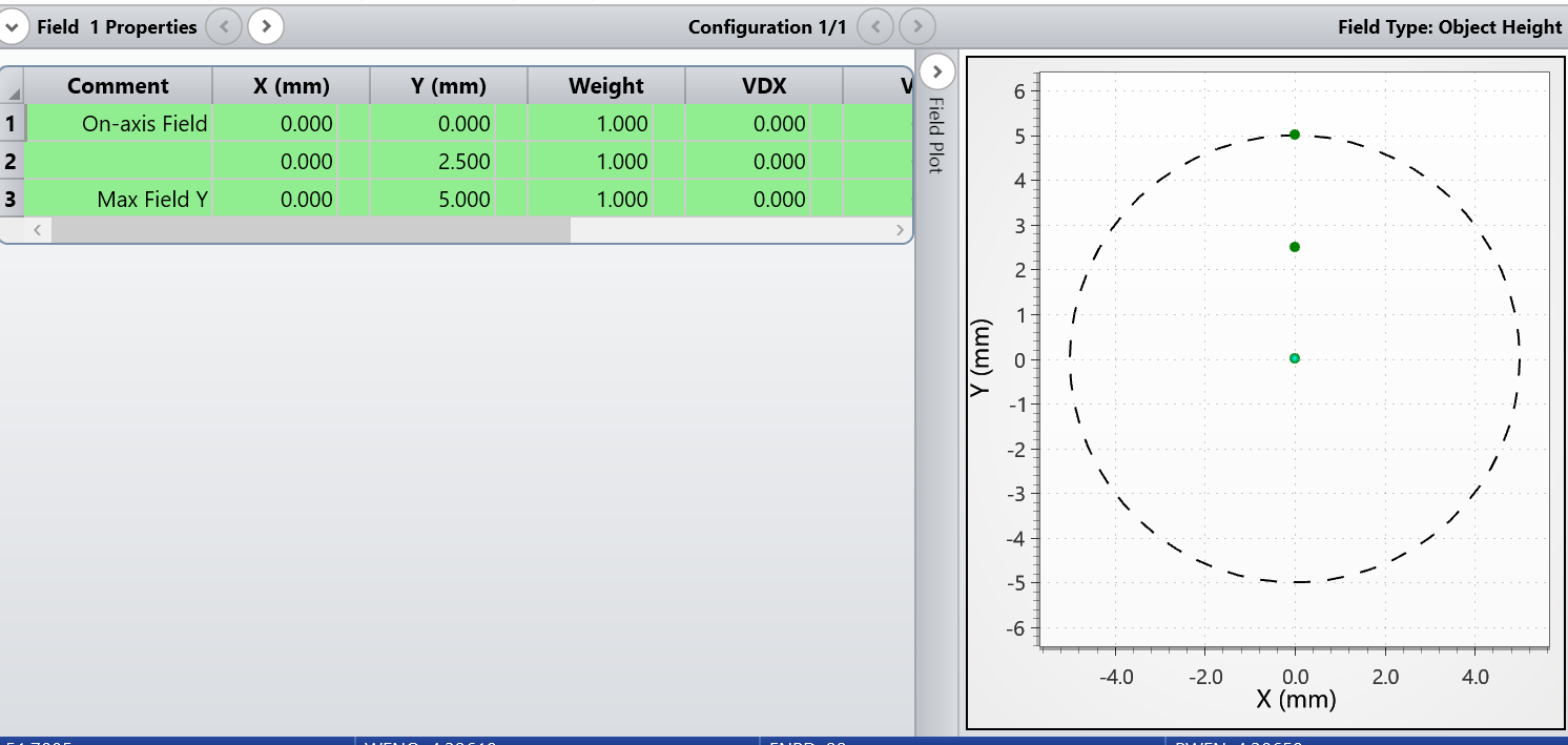
In that condition the Full Height of my Object would be 2*5(mm) = 10 (mm).
Now I want to simulate, for example, how will appear my image in my system. To make my simulation more real, I want consider my camera sensor that is a 2048 x 2048 pixels with pixel size of 6.5 microns. I want to further optimize my simulation, therefore I am gonna to create a new image with the dimension of the pixels that matches the dimension of the pixel of the sensor.
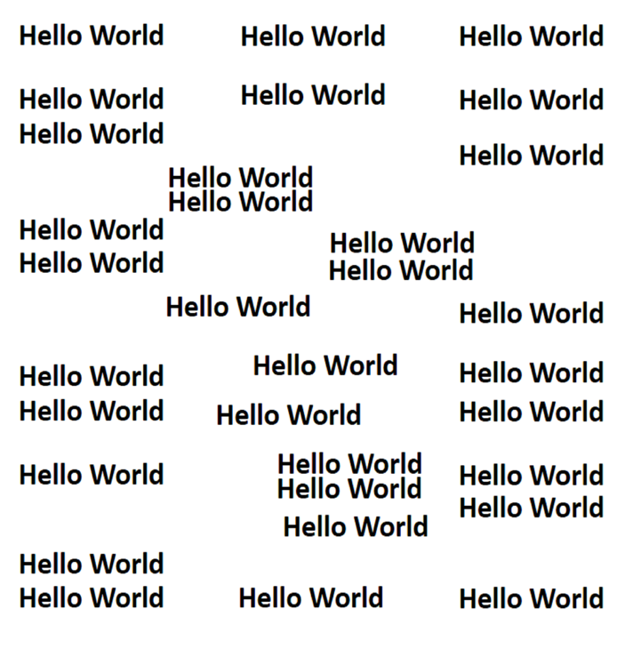
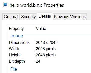
So in this condition I am filling the empty space of the Image Simulation tool as following:
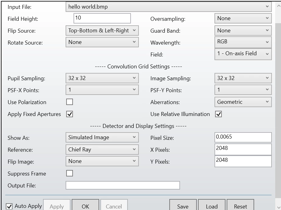
The image I do get is the following:
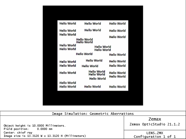
My questions are the following:
- Why do I have a black frame around my picture if I scaled it in order to match the pixel size of the sensor? in this case the Image size is 13.312x13.312 resulting from size of camera pixels* size of X/Y pixels. Does the image size is referred to the total image (including the black) or only the image inside?
- If I put Pixel Size, X pixels, and Y pixels equal to 0 as default I do get different results in term of image size.
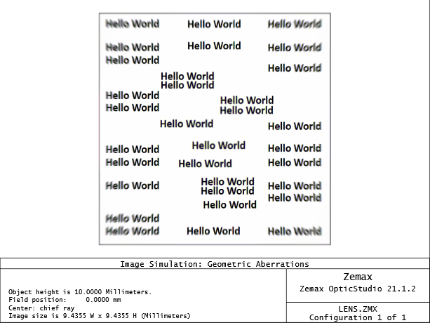
So is it just because by default the pixel size is different?
thanks in advance.

