Hi Matteo,
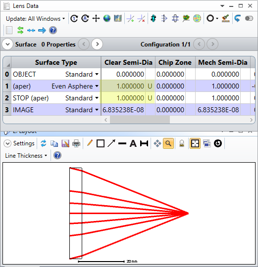
The Quick Focus tool will only be able to adjust the back focal distance to try to achieve the desired criterion. In other words, only the thickness of the surface before the Image will be updated with this tool. Is that the only variable in your system? If you have more than that, I would recommend using a local optimization to find the best focus. We have some guidance on setting up a spot size optimization in the Knowledgebase article 'How to design a singlet lens, Part 3: Optimization.'
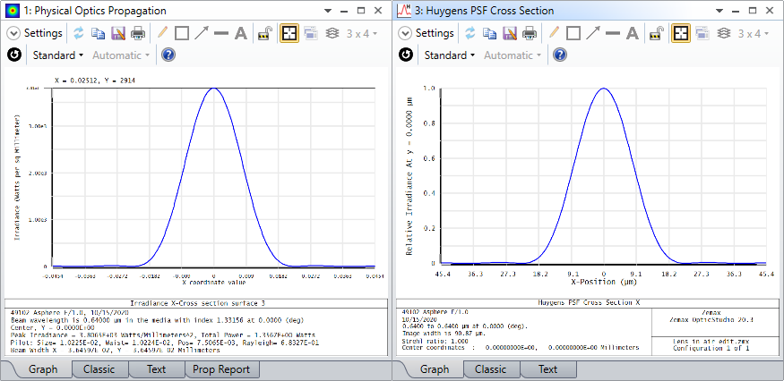
With respect to your second question, I would usually recommend using Huygen's PSF for a system with a GRIN lens. This is because of how POP deals with GRIN lenses. The Physical Optics Propagation tool focuses on wavefront propagation instead of ray-based propagation. This allows us to inspect coherent self-interference effects of the beam that geometric ray tracing would not capture. However, this propagation method is not used for a GRIN lens. Rather, POP treats a GRIN lens in the following manner:
- At the front of the lens, decompose the beam into a grid of rays
- Use the rays to propagate through the GRIN zone
- After leaving the GRIN zone, synthesize the new complex beam distribution by the rays’ information (direction, intensity, phase)
- Continue propagating with the diffraction method after the GRIN zone.
In this way, POP will be treating a GRIN lens in a similar manner to how the Huygen's analysis would act. In both cases, each method uses rays to travel through the GRIN lens, then considers diffraction effects at the final step of the synthesis. Because both are performing a similar set of steps, Huygen's is usually preferable because it doesn't require the additional setup and inspection that POP does.
Regarding your last question - that method of checking for convergence is a good one. If you're not seeing convergence for such a high sampling rate, it could be that there is some other problem in the POP analysis. Have you checked the Prop Report for any errors? Additionally, have you checked the beam phase surface-by-surface for any aliasing effects? If you haven't already, I would recommend taking a look at our Knowledgebase article series on using POP. This will provide some guidance on the steps you can take to make sure your POP settings are adequate. The first article in the series is here: 'Using Physical Optics Propagation (POP), Part 1: Inspecting the beams.'
Let us know if you have any other questions!
Best,
Allie
Thank you so much for your answer, Allie. Your information is really helpful!
About point 3, i didn't get any warning in the prop report, but i didn't check the beam phase surface by surface. I will perform this check and I'll get back in case the problem is not solved.
Best,
Matteo
Hi Allie,
I would have a follow-up question. I performed several tests with a single asspherical lens and I found that POP returns the same FWHM and Beam waist at the spot size that i calculate with the analytic formulas for gaussian optics.
For example, for a Gaussian beam with aperture=2mm and f=50mm at 640nm, the POP calculates a FWHM of 12um, which is exactly what i would expect from the analytical formulas. Instead, Huygens PSF measure FWHM=18.2um, which is a quite different value. Can you explain why we see this mismatch?
Also, can I still be confident that Huygens PSF will calculate the correct values for a system with GRIN lens, even if the results seem to be not accurate for a simple lens?
Thanks,
Matteo
Hi Matteo,
For a discrepancy like this, I would be sure two check two things:
1. Is the sampling adequate in both tools? In particular, does the Prop Report in POP have any errors? Additionally, have you matched the sampling between both tools?
2. Have you declared a Gaussian Apodization in the System Explorer...Aperture tab? This would ensure the ray-based calculations (like Huygen's) are seeing a gaussian intensity distribution.
If you have confirmed both those points and are still seeing an error, could you send the file in? If it is confidential, we can move this to a MyZemax case. In either case, please send the file as a Zemax Archive (ZAR). This file format can be created by navigating to File...Create Archive. Once I have the file, I will be able to speak more definitively on the reason for the discrepancy!
Best,
Allie
Hi Allie,
Thanks for your prompt response. The POP returns the result expected from the analytical formulas, so I assume the sampling is correct. As for the Huygens, it seems that the solution is converged, as the result is the same for different samplings.
Also, yes, I have declared a Gaussian apodization.
I attached the file as .ZAR. Please let me know if you need any other info, and thanks again for your help!
Best,
Matteo
Hi Matteo,
Thanks for sharing your file here! It seems like the main reason for the discrepancy is due to the fundamental difference in where each analysis starts generating their data. In the Huygens PSF, the results are entirely ray-based, so the bundle of rays as defined by your Aperture Value (set to EPD = 2mm in the System Explorer for your model) are strictly what is used for the computation.
POP, on the other hand, will input a Gaussian beam as set by your Beam Definition tab. This means that while you can define a Gaussian Waist of 1mm (like you had done) in POP, the beam itself will cover more than the area defined by the waist. So, in your case, your POP beam covers more area than the 2mm EPD ray-based calculation, and since your lens had a Clear Semi-Diameter of 11 to 12mm, this POP beam wasn't really being truncated at all. If I resize your singlet to have a 1mm Clear Semi-Diameter, the POP beam is clipped to have the same profile as the rays in your system, which makes the two analyses match:
Alternatively, you could also increase your EPD value and modify your Apodization Factor so that your 1/e^2 point is at the correct location/defines the desired beam waist.
Please let us know how these thoughts work out for you and if you have any more questions here!
~ Angel
Hi Angel,
Thanks for your detailed explanation. I would have some follow-up questions:
1) When I set the Entrance Pupil Diameter = 2mm, and I set the Apodization Factor to be 1, I'm essentially modeling an input Gaussian beam waist (defined as the width at 1/e^2 of the peak intensity) of 2mm, correct? As for the POP, Waist X and Waist Y represent the radius of the Gaussian beam waist. Therefore by setting them to 1mm, I would expect to model a Gaussian Beam Waist of 2mm, matching the ray tracing one. What do you exactly mean by 'the beam itself will cover more than the area defined by the waist', and how can I make sure that I can properly model the desired Gaussian input beam in POP?
2) As I mentioned in my last post, the POP gives the same results that I calculated analytically for a Gaussian beam diameter of 2mm and f=50mm. How can I modify my Huygens PSF to get the same results as the POP (and not vice-versa)? Of course, I could increase the Aperture Value until I get the desired spot size, but then my input beam diameter (waist) would not be 2mm anymore.
Thanks,
Matteo
Hi again Matteo,
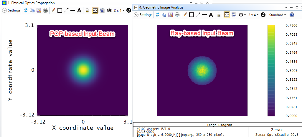
The main point I was trying to make in my previous post was that while you are defining a beam with your rays with a beam waist equal to 1mm, the maximum extent that will ever be traced by your rays will only go out to 2mm in diameter. This is in contrast to POP, which will not stop defining the irradiance profile of the beam at 2mm in diameter. Hopefully to make it clearer from my end, I slightly modified your system by adding in a dummy surface at Surface 1, making the aperture quite large, and setting up POP to start and end at Surface 1. This just yields the irradiance profile on the dummy surface. I can use Geometric Image Analysis to obtain an irradiance profile on the same surface, but with the ray-based beam instead, showing how the rays currently represent the central 2mm diameter region:
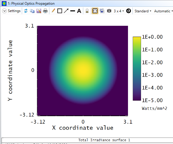
So, you can see that the rays are inherently 'clipped' in their definition. If I adjust the 'Scale' of the POP output to show in terms of 'Log-5', we can see a more fuller extent of the POP beam as well:
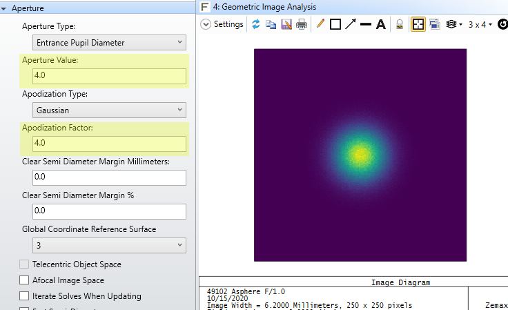
So, to make Huygens PSF match more closely with the POP output, what we need to do is expand the EPD value so that rays are not truncated at the 2mm diameter part of your beam. Subsequetly, we also need to change the Apodization Factor to ensure that we retain the same beam waist. One definition we could use is an EPD of 4mm with an Apodization Factor of 4.0:
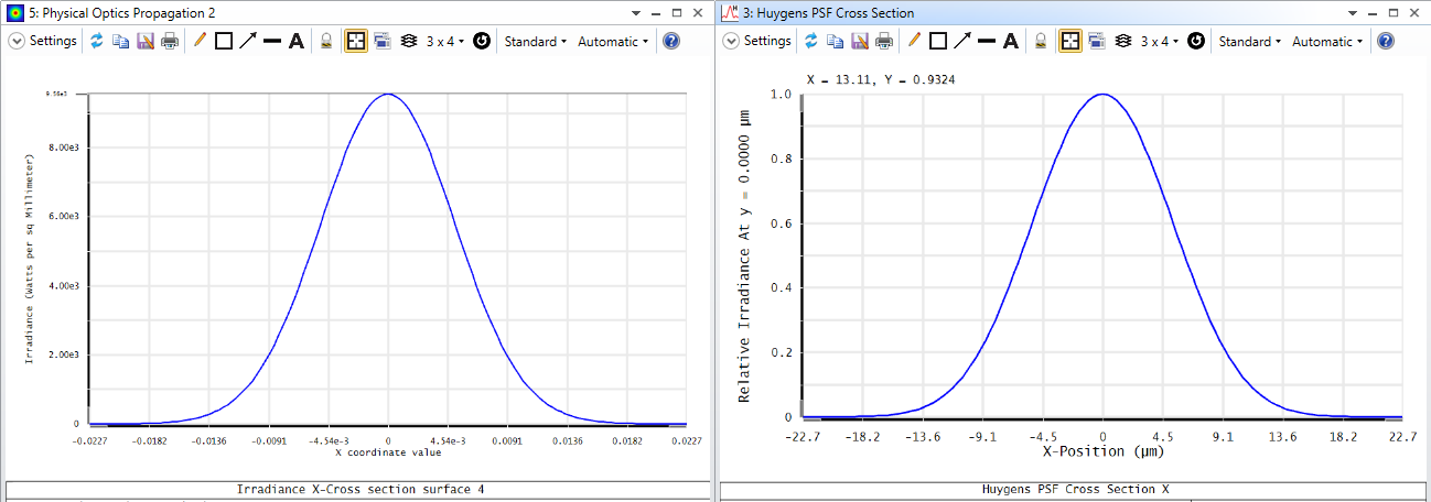
With that adjustment, the Huygens PSF now matches more closely with the POP result:
Though I linked to it in my last post, I didn't specifically call it out, so I would recommend taking a look at this article here for a bit more discussion on tweaking the Apodization Factor for your desired distribution. We also have some comments on this setting in our Help Files at 'The Setup Tab > System Group (the Setup Tab) > System Explorer > Aperture (System Explorer) > Apodization Type.'
Please let us know if you have any more questions here!
~ Angel
Hi Angel,
Now everything is clear, than you very much!
Best,
Matteo
Hi again Matteo,
The main point I was trying to make in my previous post was that while you are defining a beam with your rays with a beam waist equal to 1mm, the maximum extent that will ever be traced by your rays will only go out to 2mm in diameter. This is in contrast to POP, which will not stop defining the irradiance profile of the beam at 2mm in diameter. Hopefully to make it clearer from my end, I slightly modified your system by adding in a dummy surface at Surface 1, making the aperture quite large, and setting up POP to start and end at Surface 1. This just yields the irradiance profile on the dummy surface. I can use Geometric Image Analysis to obtain an irradiance profile on the same surface, but with the ray-based beam instead, showing how the rays currently represent the central 2mm diameter region:
So, you can see that the rays are inherently 'clipped' in their definition. If I adjust the 'Scale' of the POP output to show in terms of 'Log-5', we can see a more fuller extent of the POP beam as well:
So, to make Huygens PSF match more closely with the POP output, what we need to do is expand the EPD value so that rays are not truncated at the 2mm diameter part of your beam. Subsequetly, we also need to change the Apodization Factor to ensure that we retain the same beam waist. One definition we could use is an EPD of 4mm with an Apodization Factor of 4.0:
With that adjustment, the Huygens PSF now matches more closely with the POP result:
Though I linked to it in my last post, I didn't specifically call it out, so I would recommend taking a look at this article here for a bit more discussion on tweaking the Apodization Factor for your desired distribution. We also have some comments on this setting in our Help Files at 'The Setup Tab > System Group (the Setup Tab) > System Explorer > Aperture (System Explorer) > Apodization Type.'
Please let us know if you have any more questions here!
~ Angel
Hi Angel,
I have very basic questions. I have understood the apodization explained above by entrance pupil diameter.
- I am not able to plot the beam in geometric image analysis. It’s giving black blue screen. Could you please help me with the setting or maybe provide the file above. It would be really helpful.
- How does the apodization work when the launch is set by other parameter (for eg. Object space NA) rather than EPD. Again i am not able to match the POP and PSF results. If you could please provide a demo, it would be really great.
Regards,
Saurabh