Solved

How to put the sample at focus of microscope objective to get the collimated beam in the back focal plan?

  • 3 June 2024
  • 9 replies
  • 181 views

Dear Zemax Users,

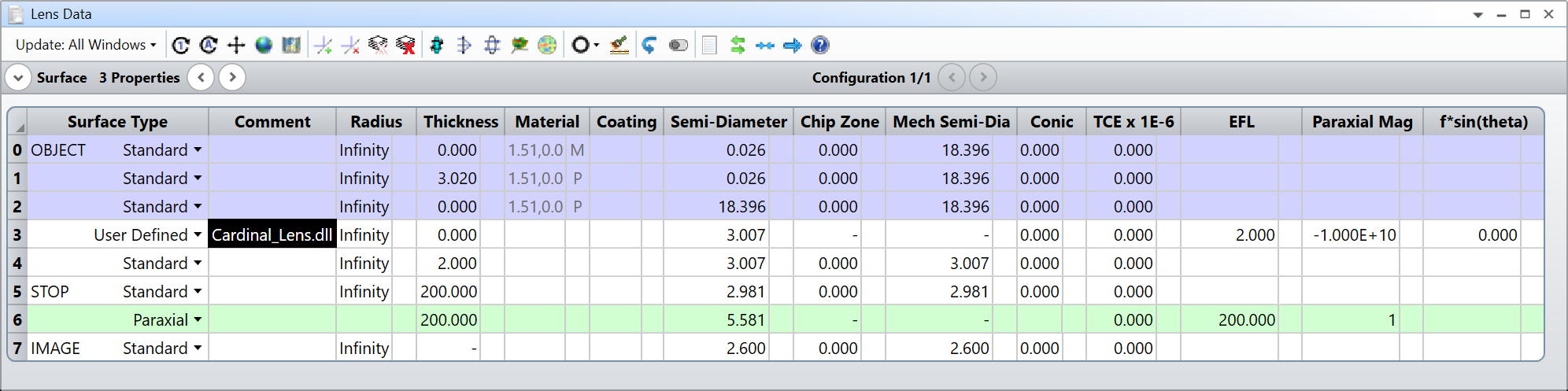
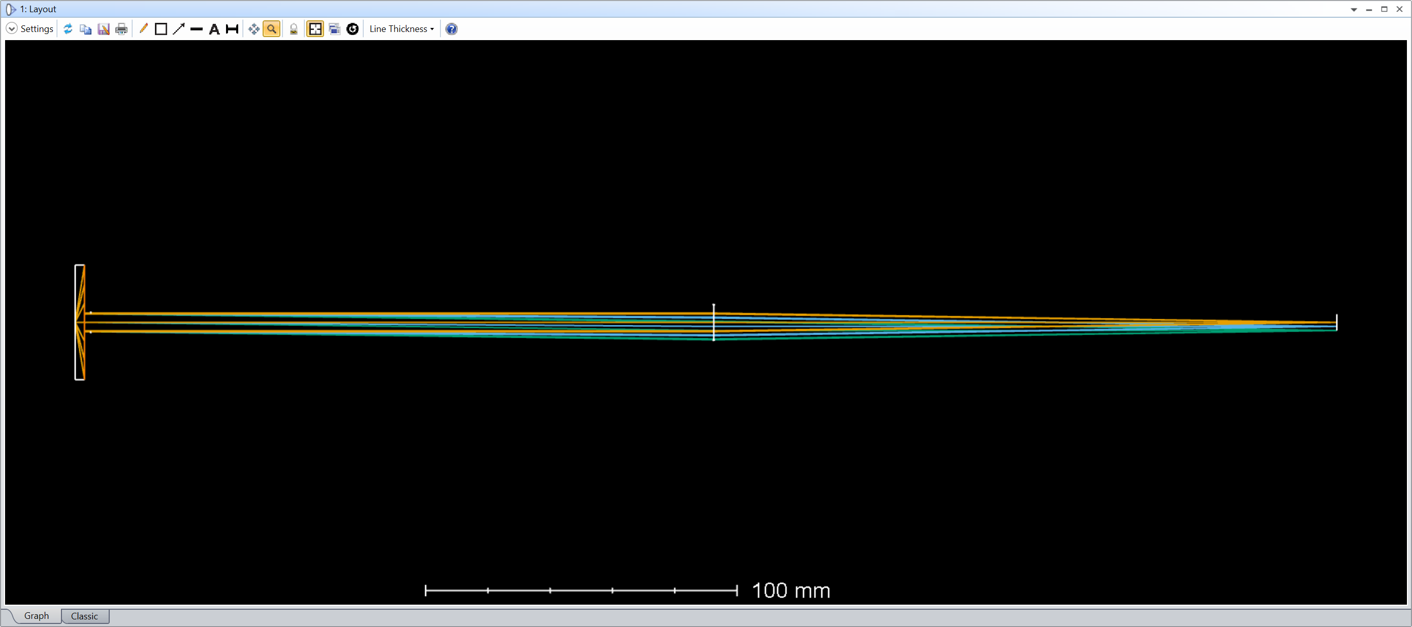
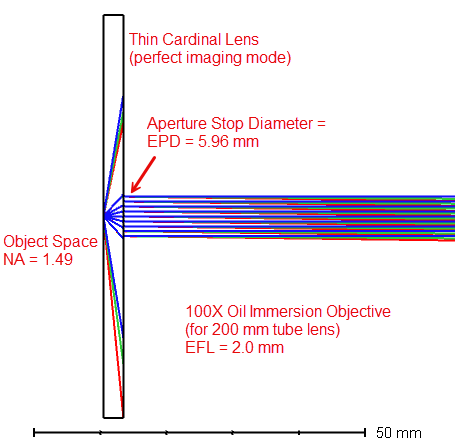
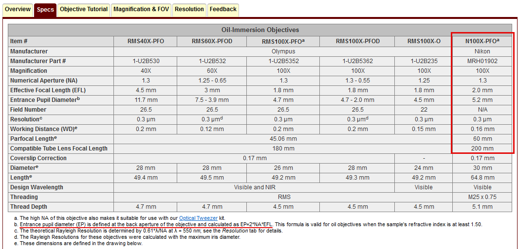
I want simulate a system where sample (has height of 26um, defined by three fields) is positioned  at a focal distance from the microscope objective (100x, NA =1.49 ) and the  collimated beam after objective is re focused by another lens (a tube lens of f= 200mm, matched with the objective) to form an image. How to make sure that the beam after objective is collimated and the image formed is exactly 2.6mm? 

Thanks.

9 replies

Userlevel 3
Badge

For example for the collimation you can insert a plano surface after objective and check angle of incidence for several points over the pupul. Or remove all components after the objective and check spot diagram in an afocal mode. 


For the image size you can check REAY (or CENY) operand for the image plane.

Userlevel 7
Badge +2

@Meena


The main issue is that you have an immersion lens and it cannot be modeled easily with a paraxial lens. Fortunately, the community is lucky enough to have @Jeff.Wilde and his extensive knowledge of rays, who wrote a DLL for the so-called Cardinal Lens for us 🚀

I let you read the details by yourself, and here is an example of the system you requested. Note that I’m assuming an immersion oil with an index of refraction of 1.51.

You can confirm the object and image height via the Merit function, which can also give you the magnification (-100X):

I’m attaching this file for your reference, when you open it, it should automatically install @Jeff.Wilde’s DLL.

Let us know if that works for you and take care,


David

@David.Nguyen 

Thanks a lot, it is very helpful. I have another question If I place another lens (with focal length of 200mm) exactly a focal length away from the image plan and relay the image of same size to camera plan by another Lens of f = 200mm (relay system is a 4f system, made of two lenses of focal length 200mm with separation of 2f in between ,   magnification = one ), what would be the size of parallel beam in between the two lenses of relay system. As I guess it would be the beam divergence half-angle times focal length  f𝜆/(𝜋𝑤0) , where 𝑤0 = image size (2.6mm) or how simulation would decide?.

Thanks.

Userlevel 7
Badge +2

Good question @Meena,


Upon reading my last post, I’m not totally sure about the size of the parallel beam in the infinity space. It seems small in retrospect. @Jeff.Wilde can you confirm that I’ve created the microscope correctly and what we should expect for the size of the parallel beam in the infinity space? My initial thought was that since the NA is 1.49, and we assume an immersion oil with an index of 1.51, the half-cone angle is about 80 degrees. The distance to the objective lens is 3.02mm, so the aperture should be 2 * ( 3.02 * tan( 80 ) ) = 36.7mm. Is there something restricting the aperture somehow?

Take care,


David

Yes You have calculated correctly @David.Nguyen , and  used a stop of diameter 6mm. Thank you. 


Userlevel 7
Badge +3

@David.Nguyen :  Thanks for your kind words and for suggesting to use the Cardinal Lens.  I modified the model slightly, converting the aperture to “Float by Stop Size” and turned on paraxial ray aiming (needed, as discussed in the paper, because the stop is behind the lens -- this way, the stop is properly filled).  Also, I placed the stop on the 2nd principal plane of the Cardinal Lens objective, which seems reasonable, particularly since we don’t know where the actual stop is located relative to the principal planes.  In practice, the beam in object space will never reach a large size because the objective has a very small working distance.  However, we can still simulate what the rays would do if we project them onto the 1st principal plane; in this case the beam would be quite large.  If we project the rays onto the curved 1st principal surface, the beam size is much smaller (in this case it’s equal to the EPD).  But again, these are just academic exercises because the small working distance will limit the beam size entering the objective.  The output beam size (i.e., the EPD) is dictated by the sine condition.

@Meena : Yes, a stop diameter of 5.96 mm yields an NA of 1.49 (for an immersion oil index of 1.51).  If you add a 1X relay to the microscope by using two f = 200 mm lenses in a 4f configuration, an image of the aperture stop is formed in between the two relay lenses, so the beam diameter there should be 5.96 mm.


We see this result is reasonable by comparison to a commercial objective with the same EFL, but a somewhat lower NA = 1.3 (Nikon N100X-PFO, sold by Thorlabs).  In this case the EPD = 5.2 mm:


Regards,

Jeff

Userlevel 7
Badge +2

@Jeff.Wilde thank you for reviewing the file and making corrections. It makes a lot of sense. I like the comparison with the 1.3NA. For me, this DLL is quite useful because a lot of my work involves objective lenses. Before I would create a paraxial telephoto lense to mimic the short working distance, but it was cumbersome to set up. Thanks a lot and take care,


David

Thanks @Jeff.Wilde for explanation. 

I have a question, if we use a 0,8x relay lens to the microscope by using  f = 250 mm and f= 200mm (M=200/250  at image plane) lenses in a 4f configuration, an image of the aperture stop is still going to form   in between the two relay lenses or this demagnification has no effect on parallel beams because parallel beam size is decided by the EPD of objective only? .

Userlevel 7
Badge +3

@Meena:  The tube lens (f = 200 mm) and the first lens of the relay (f = 250 mm) will form an image of the objective’s exit pupil (aperture stop) in the back focal plane of the first relay lens with a magnification of 1.25 (=250/200).  This assumes that the separation between the objective and tube lens is 200 mm.  You can modify the model I attached previously in order to investigate the details.

Reply