I am trying to simulate an already existing illumination system in zemax.
In order to replicate the exact system, I need to place
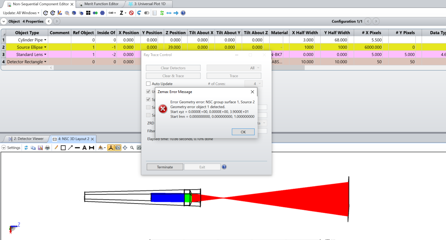
multimode Optical fiber end (which is considered as source ellipse in the simulation) & Standard lens inside a focusing tube (Which is considered as cylinder pipe in the simulation).
While I have placed both of the in the simulation and tried ray trace it. It is giving me an error as shown in the image below. Also, while plotting the universal plot It is giving me an error such that some of the operands cannot be computed.
Please provide me suggestions to solve these errors
.
Kindly find the attached zemax file.
Thanks in advance
Best Regards,
Suguna
Best answer by Ethan
Hi @Suguna,
It looks like you did not include a .ZMX or .ZOS file in your ZIP, so I’m not able to look at your design, but from the screenshot, the Inside Of options are correct. Geometry errors are are not necessarily an indicator of a bad simulation or design. In a perfectly good system, sometimes a few rays can land exactly on the boundaries between surfaces, and OpticStudio cannot accurately calculate the intercept. With that said, if you have a lot of rays failing to trace, you likely have a problem with your geometry.
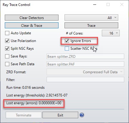
If you select Ignore Errors, the ray trace should complete successfully without terminating the trace. Instead the rays that experience an error are grouped in the “Lost energy (errors)” result. If this number is high, it indicates that there is a problem with your system; if it’s a very small number, it likely means that a few rays ran into a boundary and could not be computed.
If you find that the Lost Energy parameter is in fact high due to errors, there is a helpful Knowledgebase article on how to locate geometry errors so that you can fix them:
Regarding the error with the Universal Plot, most analysis features in OpticStudio require computed rays so that they can perform their analysis; therefore, until you successfully run a ray trace, these features have no data to consider and will give you errors or missing results.
It looks like you did not include a .ZMX or .ZOS file in your ZIP, so I’m not able to look at your design, but from the screenshot, the Inside Of options are correct. Geometry errors are are not necessarily an indicator of a bad simulation or design. In a perfectly good system, sometimes a few rays can land exactly on the boundaries between surfaces, and OpticStudio cannot accurately calculate the intercept. With that said, if you have a lot of rays failing to trace, you likely have a problem with your geometry.
If you select Ignore Errors, the ray trace should complete successfully without terminating the trace. Instead the rays that experience an error are grouped in the “Lost energy (errors)” result. If this number is high, it indicates that there is a problem with your system; if it’s a very small number, it likely means that a few rays ran into a boundary and could not be computed.
If you find that the Lost Energy parameter is in fact high due to errors, there is a helpful Knowledgebase article on how to locate geometry errors so that you can fix them:
Regarding the error with the Universal Plot, most analysis features in OpticStudio require computed rays so that they can perform their analysis; therefore, until you successfully run a ray trace, these features have no data to consider and will give you errors or missing results.