Hello Sandrine, 
Is there also a way to optimize the smallest overall spot of the whole field? I can’t find the right merit function operand. 
Thanks in advance!
 

Hi Lea

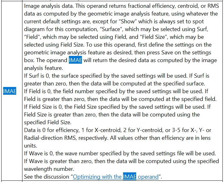
Have a look at the IMAE operand. That operand is basically returning data from the geometric image analysis feature. You give the size of the field and it returns the image as a spot diagram. Then the IMAE operand can calculate the size of the spot, etc….
You can optimize for the smallest spot.
 

This operand is used for multimode fiber coupling: How to model multi-mode fiber coupling

Let us know if you still have questions.


Hi Sandrine, 

is it possible to get the 1/e² radius of this image?

Thanks!
Lea


Hi Lea,

The Optimization Wizard will give you the smallest RMS spot size, averaged over fields and wavelengths, using whatever weights you give them. Does that help?

  • Mark

Hi Mark,

thanks for your reply. I think it helps when I give some additional information to my question:
I want to simulate a laser beam after a multimode fiber with a fiber core diameter of 200 µm. For this purpose Sandrine suggested setting up the system with an object space NA and using multiple field points (fiber optic focalization | Zemax Community). For optimizing the whole field I use the geometric image analysis. 
Now I want to compare the beam size I get in the simulation to the one I have measured in an experimental setup and I am not shure how to do this best. When measuring the beam I can compute the diameter of the beam with different definitions (1/e², 4 sigma, FWHM, …). Is there a way to receive the beam size of the simulated beam in one of these definitions too?


Thanks for that extra information. Sandrine’s advice is exactly correct. You might want to use Telecentric object space as well, so each point on the object surface radiates into the same cone angle irrespective of the subsequent optical system.

What do you want the subsequent system to do? Is it forming an image of your fiber, or are you trying to produce a region of uniform intensity to give a uniform illumination?


Hi Lea,

The output of a step-index multimode fiber is typically a uniform round spot spatially, uniformly filling a cone in angle space.  This assumes that all of the fiber modes are excited as would be the case with an overfilled launch (i.e., a launch beam having an NA that equals or slightly exceeds the fiber NA).  An underfilled launch may create a different output spot, depending on how long your fiber is and how many bends/turns it has that can create mode coupling.  If you are using a laser as the source, the fiber output spot will of course be highly speckled, but it can typically be modeled with rays by assuming the outgoing beam is smooth and uniform, both spatially and in angle space (at least for the overfilled launch case).  As Mark mentioned, for MMF modeling, it’s best to use the Telecentric Object Space setting.

I assume you are using some sort of beam scan device to experimentally measure the spot size.  In OpticStudio, as you may know, the IMAE operand can provide the beam radius in terms of rms values (x-, y-, and/or radial).  If your device can provide similar values, then you should be able to easily make direct comparisons.  Otherwise, if you need some other measure of beam width, then I believe you need to export the Geometric Image Analysis results to a different software package, like Matlab, for separate analysis (or use the ZOS-API to do the same thing in a more integrated fashion).

Regards,

Jeff


Reply