Hi all,
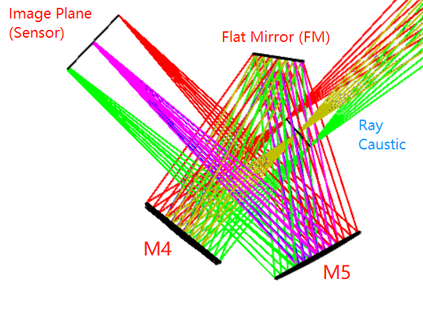
I have a very fundamental question about modelling FOV scanner used for telescope system. Below I attach a picture showing that the ray caustic from the Three Mirror Anastigmat (TMA) forming a very good image at the intermediate image plane. (I don’t show the plot of the TMA system). And we use M4, Flat Mirror (FM) and M5 to form a basic FOV scanner system to shrink the size of the sensor.
For example, we can tip & tilt the flat mirror to make almost each filed point (on & off axis) hit at the center of sensor (the pink ray bundle in the picture) which means the green and red ray bundle almost concide with the pink ray bundle . I start with only on-axis field and optimize to achieve a diffraction-limited system. However, when I use multi-configuration function to add more off-axis fields, for example (0 , 0.02 deg), and try to tilt the flat mirror, the system works very bad for off-axis field, I am just curious if any one have some inputs or suggestions, that would be very helpful!
Thank you!