Solved

how to model light absorption in an absorptive slab(cavity)

  • 10 October 2023
  • 3 replies
  • 114 views

hello all,

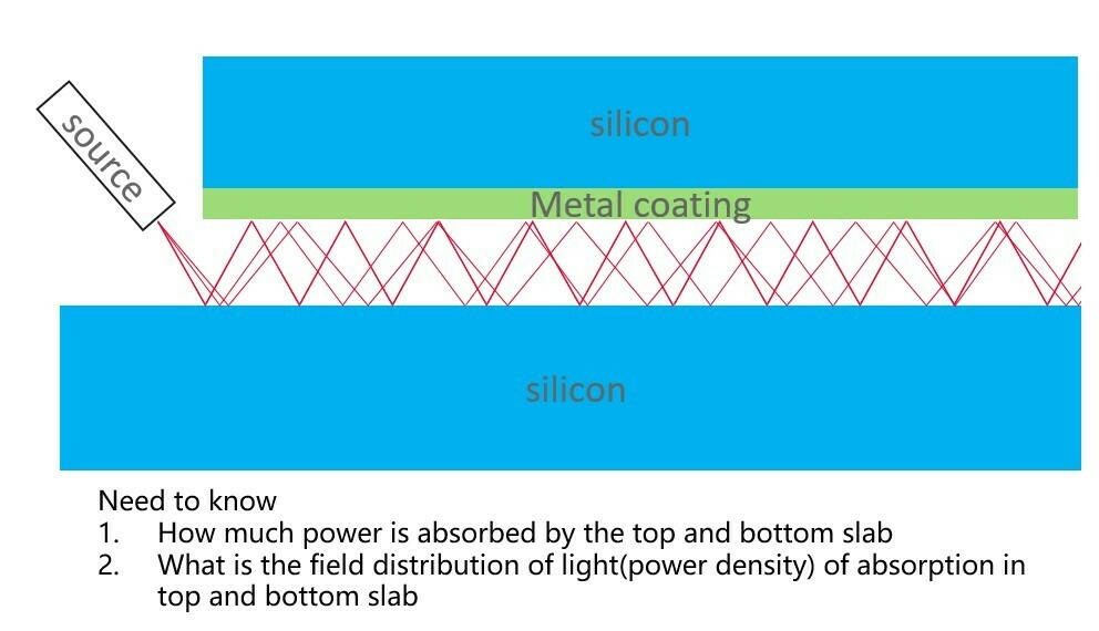
I am trying to simulate a two slab cavity absorption. 

As shown in the picture, the light is emitted from the side of the cavity. and the top and bottom cavity are made of silicon, which has an complex refrective index in visible wavelength. and also the top slab is coated with Pt, which can reflect most of the light but still got around ~7% absoption. 

My goal is to calculate

  1. How much power is absorbed by the top and bottom slab
  2. What is the field distribution of light(power density) of absorption in top and bottom slab

two issue I encountered now

  1. I dont know how to model a material with complex refractive index. It seems the transmission property of materials catalog do not deal with polarization and incident angle? And how about the absorption in metal coating?
  2. for the power density, I put a detecter in between the slabs, due to multiple reflection in the cavity, the total power it returns is larger than the input power of the source. By setting the detector ‘front only’could still not solve this issue. 

Any idea how to model this absorptive cavity?


icon

Best answer by Andrew_Davies 4 January 2024, 18:44

View original

3 replies

Userlevel 2
  1. Use Detector Volume to calculate total absorbed power and its profile
  2. The SILICON material in INFRARED catalog does not include the visible range, so you’ll have to create a custom material for your purpose.
  3. Your get more power than what you inserted since the detector sees multiple zigzags on it, meaning its counting each ray multiple times
Userlevel 1
  • You can use coatings to model the metal with a complex refractive index. See the Coating Group section in the Zemax helps file for more information. Note that if the spacing is within a wavelength you may need to add a Etalon coating. 
  • I would make your two rectangular volumes of silicon. Then I would add a coating to the front surface of the top Silicon rectangular volume. 
  • A simple way to find out how much is absorbed in the coating is to turn the imaginary index to zero in the coating material file and see this change it total energy at the output of the slab.
Userlevel 1

Sorry I can’t edit comment and submitted before I finished. I meant to say 

  • I would make three rectangular volumes. Two of them with material silicon and the middle one air. Then I would add a coating to the front surface of the top air rectangular volume. Make sure to take nesting into account.


Reply