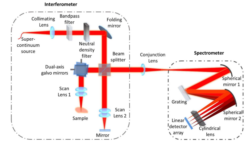
I am trying to model a 2-axis galvo with double pass, but the interface suggested that the coordinate system will not function correctly. Is there anything I can do to make the simulation happen, or do I have to do non-sequential modeling?

Hello Yehe.Liu


If you have access to Zemax Zebase you may find this model useful:

Double-Pass Lens With Beamsplitter and Tilting Mirror

(Source: ZEMAX Development Corporation Mirror scans through +/- 0.5 degrees)


In addition, I hope this article helps you out 

https://opg.optica.org/ao/abstract.cfm?uri=ao-54-32-9554

Qun Yuan, Dan Zhu, and Zhishan Gao, "Alignment analyses of a galvanometer-based scanner in free-space Fourier domain optical coherence tomography," Appl. Opt. 54, 9554-9562 (2015)


In Zemax knowledgebase and literature, you can have a look at these too;


Hi all,

@Önder.Sönmez - Thank you for sharing these great resources!

@Yehe.Liu - When you are about to use the Make Double Pass tool, it does warn that it may not work with Coordinate Breaks. However, that is not a guarantee. I would suggest trying the tool first in Sequential Mode. You can check it to make sure the Coordinate Breaks were applied appropriately. Be sure to save a copy of your original system first so that you can always refer back to it as you validate the double pass version. 

As an example, I put together a double pass galvanometer using a file we generate as part of the Optical System Design course on OpticsAcademy. It is attached. In the file, I set up the galvanometer, then used the Make Double Pass tool. When you open the file, you will see that there are two layout views. The left layout shows the first pass, the right layout shows the reflected pass. As you can see, all of the optics are placed correctly. The only difference between the two passes is the spread of rays in the off-axis beams. This difference is due to the angle of incidence of those beams upon the reflecting mirror (surface 10). 

If for some reason the Make Double Pass tool doesn’t work, you can still update the system manually. In that case, you should make use of Coordinate Returns to help you place your surfaces. You can read more about those here: How to restore coordinate systems using the Coordinate Return – Knowledgebase (zemax.com)

Thanks! @Allie @Önder.Sönmez 

The warning was worrisome, but all worked out.


Reply