

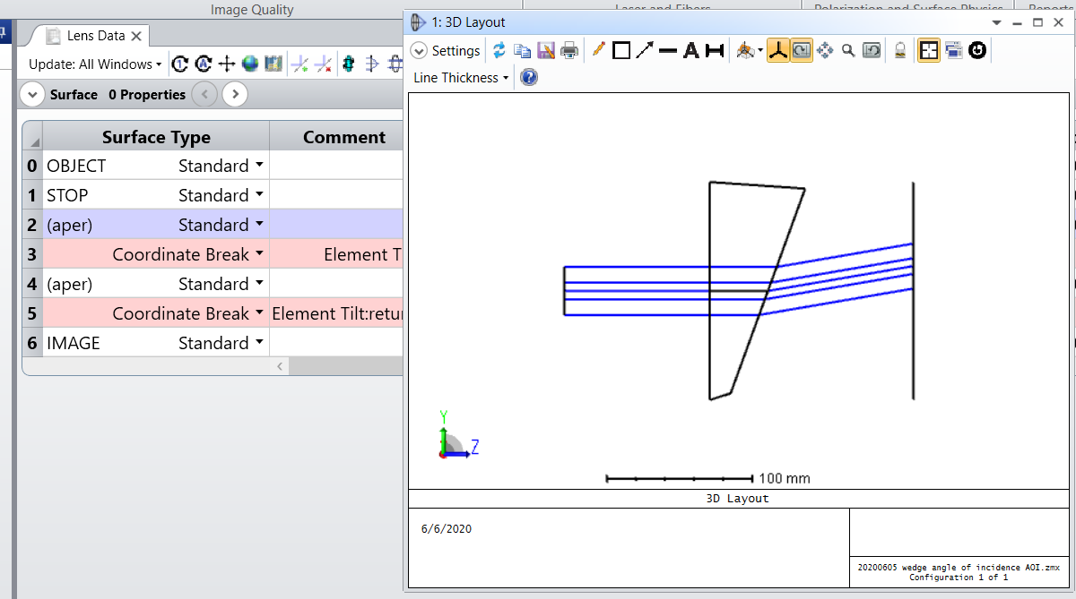
A user is asking how to make 3D layout draw properly a cylinder with tilted back face and subsequently export this part to CAD STEP file. When I tried using Coordinate break to tilt the back face, the layout appears funny and the CAD STEP part exported follows the layout appearance, which is not the right angle circular cylinder the user expected.
In this case, there are two ways to fix this:
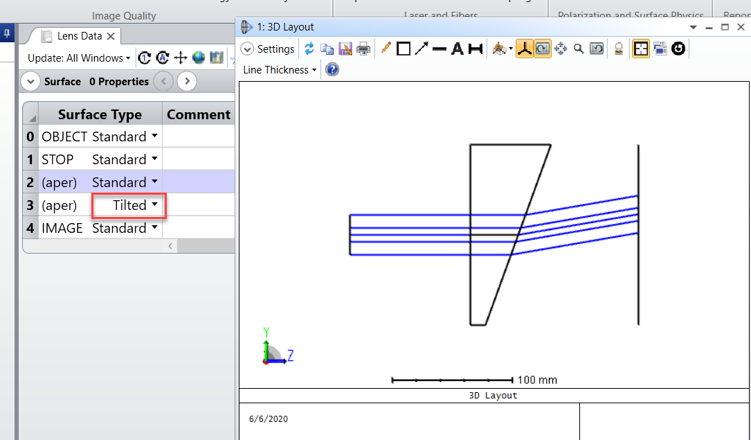
1. Instead of using Coordinate Break surface to tilt the back face, use Tilted surface type instead.
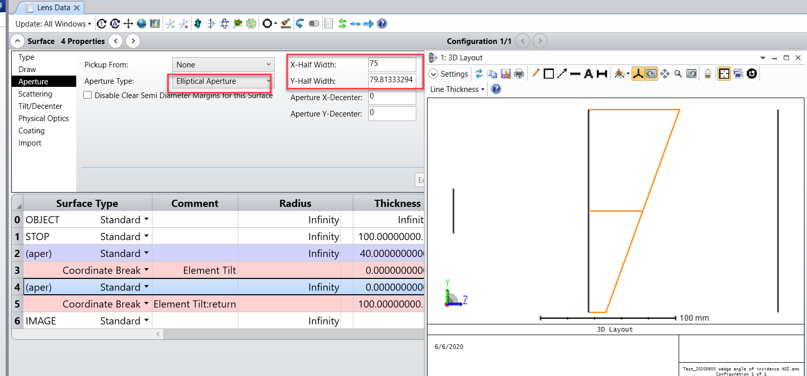
2. Alternatively, you can also apply Elliptical Aperture on both the front and the back face of this part. On the front face, the Elliptical aperture will have the same X and Y radius, while on the back face, the Elliptical Aperture X radius will remain the same as that of the front face X radius, while Y radius needs to be set to 'Y_radius_front face / Cos(tilt X angle)'.
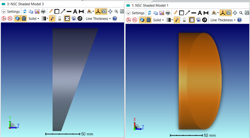
Now if you run CAD export on this part, you'll see a nice right angle circular cylinder.
Best regards,
Hui