My current project is to simulate output rays from a fiber bundle with 710 fibers (0.22 NA) arranged in 5.8mm core diameter as shown in the attached file. Which is the best way to design the source with specification mentioned above? In sequential or non-sequential mode and How? And my aim is to get all the rays focused or collimated to a detector with 17mm diameter.

Solved
How to design an optic fiber bundle?
Best answer by David
Hi Dion,
*** I have edited this post to correct an oversight. For most purposes, the design should be telecentric in image space.
If it is not necessary to model the fiber bundle in detail, the bundle could be modeled in non-sequential mode using a simple source such as a Source Two Angle to model the bundle emission without modeling the individual fibers.
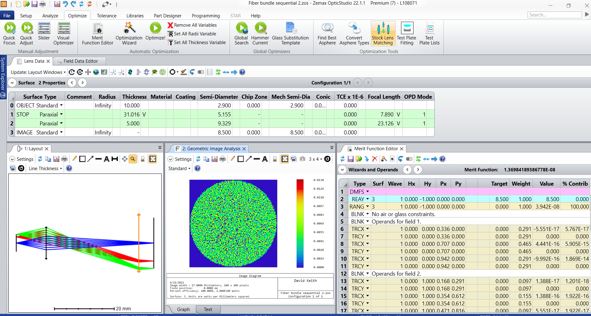
However, the design could also be implemented in sequential mode where optimization is more effective. In the attached design, the aperture is set to an Object Space NA of 0.22 to model the fiber emission divergence, and also to Telecentric Object Space to model the fact that the emission from each fiber is directed along the fiber axis. The field is set to Object Height with the maximum field at 2.90 mm which is at the edge of the 5.8 mm diameter.
Since you want to form a light body that has a 17 mm diameter, in a simple design this will be an image of the fiber bundle core. A single paraxial lens is used in this example. The distance from bundle to lens is fixed. The distance to the image where the image of the bundle will be formed is variable, and so is the focal length of the lens. These two variables are sufficient to allow optimization for image quality and for the size of the light body. A second lens is used to cause the light forming the light body to be telecentric in image space. An RANG operand is used to target that, and the focal length of the second lens is the variable which allows this added condition
The Optimization Wizard is used to construct a merit function that optimizes image quality. An REAY operand is added to target the ray from the edge of the field (edge of the bundle) to land on the image plane at the height of 8.5 mm, which will be the edge of the light body. Optimization then determines the distance from lens to image and the focal length of the lens.
As a further verification, Geometric Image Analysis is used to model the light footprint on the image plane.
You also mention collimation. It is not possible to specify the size of the light body on the image plane and also the divergence of light in the light body. The magnification of the system is 17/5.8 = 2.93. The divergence of the source is 12.7 degrees half-angle (NA 0.22) so the divergence of the light body will be 12.7/2.93 = 4.33 degrees. This calculation assumes something called ‘conservation of etendue’. (Strictly speaking, etendue is not conserved; it is like entropy -- it can increase, but never decrease.) I won’t go into this since there is plenty already written on it. You might also read about the ‘Lagrange Invariant’.
I have attached a zip file containing the design both as a zar and as a zmx file.

Enter your E-mail address. We'll send you an e-mail with instructions to reset your password.
Need more help?
To Chinese users:
Do not provide any information or data that is restricted by applicable law, including by the People’s Republic of China’s Cybersecurity and Data Security Laws ( e.g., Important Data, National Core Data, etc.).
不要提供任何受适用法律,包括中华人民共和国的网络安全和数据安全法限制的信息或数据(如重要数据、国家核心数据等)。