Question

How to control the secondary scattering for reflecting surface with BRDF applied?

  • November 12, 2025
  • 4 replies
  • 26 views

jsung
Ultraviolet
  • Ultraviolet
  • 28 replies

When we use BRDF file for reflective scatter on reflector or hollow pipe inner surfaces, I normally set it like this to split incident rays to 50% specular and other 50% diffuse scattering.

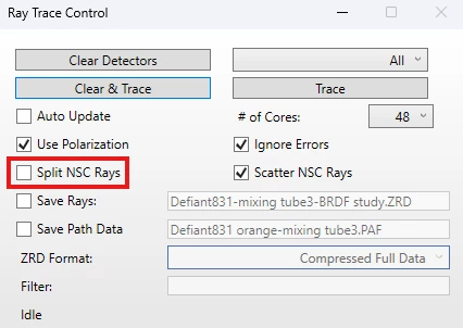
Question is then should we use "ray split" option in the ray trace control below? If this box is unchecked does Zemax not produce secondary scatter when first scatter rays bounce again off the reflecting surface?

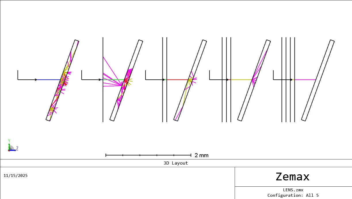
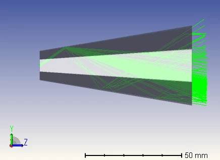
I copied screen shots of these settings and 3D view of the hollow pipe model for testing it below.


Regards

JS

4 replies

MichaelH
Ansys Staff
Forum|alt.badge.img+2
  • Ansys Staff
  • 411 replies
  • November 14, 2025

Hey JS,

In general, yes, you need to have Split NSC Rays checked when performing an operation like scattering where you one incident ray to become multiple output rays; otherwise, OpticStudio will only trace the specular ray from the interface.

In non-sequential ray tracing, each segment of a ray is ~208 bytes (I think it has increased in recent releases to around 240 bytes with a few more values being tracked), so always enabling ray splitting can be a costly decision that potentially crashes OpticStudio if you’re tracing a lot of rays on a low-powered computer.  With ray splitting enabled, every ray-face interaction produces two segments, so this is an exponential growth when a lot of rays or a lot of surfaces are present.  According to the Help Files, even a small number of rays of 100,000 with 50 segments (50 ray-face interfaces) produces a ZRD file that is 1Gb.  So, to provide flexibility to the user, ray splitting is off by default but can be enabled for both Layouts and Ray Tracing.

Note that simply checking Split NSC Rays might not produce the expected results in your case.  There are other considerations like minimum relative ray intensity, the NCE nesting rule, TIR (scattering is ignore for TIR interactions), and other scenarios that might affect the expected result.  If checking Split NSC Rays does not produce the expected results, I would recommend sanitizing your file and uploading it to this forum so other members can help to identify the root problem.  

~Michael


jsung
Ultraviolet
  • Author
  • Ultraviolet
  • 28 replies
  • November 14, 2025

Hi Michael,

Thanks for your feedbacks on this question. Yes, I’m aware of memory impact of turning on the ray split in the ray trace control. So, I normally have the “simple ray splitting” checked in the non-sequential system explorer, which will have Zemax handle the ray split on every surface in statistical way instead of doubling the specular rays at each refracting surface. So, it conserves the total number of rays during the ray trace.

After posting this question a few days ago I tinkered with some combination of settings and got these two main observations. “Simple ray splitting” is checked in all cases.

  1. If the ray split box is off in the ray trace control and scatter fraction is somewhere under 1 like 0.5, the reflective scatter surface with BRDF will still scatter, but in statistical way. So for 100 incident rays to scatter surface 50 rays will reflect in specular direction and other 50 rays will go in scatter directions. So this setting combination won’t increase the total number of rays traced, but signal to noise ratio won’t be great unless I use larger number of source rays.
  2. If the ray split box is check on in the ray trace control and scatter fraction is like 0.5, Zemax will create extra scatter rays defined in number of scatter rays box in addition to the main specular reflection ray. So this setting will make more total rays depending on how many rays is set in the number of rays for BRDF scatter.

I have found the setting 2 above will result in better signal to noise in the color detector showing mixed color from the multi-color array sources for the same name of source rays.

Still, what I’m not very sure is if the “Maximum Intersections per Ray” setting in the non-sequential system explorer applies to only main specular rays or also to secondary child/scatter rays, though there is also minimum ray intensity setting that will terminate weak powered scatter rays at some point.

Regards

JS


MichaelH
Ansys Staff
Forum|alt.badge.img+2
  • Ansys Staff
  • 411 replies
  • November 16, 2025

Hi JS,

The Maximum Intersections per Ray is on the parent ray; any child rays from scattering are still considered to “originate” from the parent and the child ray inherits the previous number of intersections.  So if the parent ray has already encountered the Maximum Intersections per Ray and then encounters a scattering event, the ray won’t split/scatter.  

If I set the Maximum Intersections per Ray to 5 (the minimum number), then once a ray encounters 5 different intersections, the ray will terminate (it will be recorded as Lost energy (errors) during a ray trace).  I have setup a simple tilted plane parallel plate with the front surface set to Lambertian scattering (10 rays, 100% scattering).  If this PPP is the first object, then the specular ray is scattered into 10 rays and each child ray can interact up to 4 more times before the energy is lost to errors (this is the far left).  On the other extreme, if there are 4 dummy surfaces before the PPP and then the ray strikes the scatter surface, no scattering will occur because the parent has already encountered the maximum number of intersections (this is the far right).


oenthus01
  • Monochrome
  • 4 replies
  • November 16, 2025

Hi Jinwon and Michael. I learned from this as well.