I am trying to understand how coordinate breaks work in Zemax, and I have a question about the tilt pivot point for a mirror. When a mirror(component) is used, the tilt pivot is typically at the back surface of the mirror(?). I’m wondering how to set this up in Zemax when using a mirror surface that has a defined thickness.
PS: I read this, and tried as file attached.
Thanks for your help
YANG
Best answer by Yang.Yongtao
Hey Yang,
I would use the 2 built-in tools to the Lens Data Editor:
Add Fold Mirror
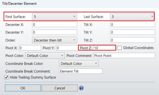
Tilt/Decenter Elements
The Add Fold Mirror will properly convert all thicknesses and radii to the proper sign convention while the Tilt/Decenter Elements tool has a relatively new feature of “Pivot About Point”. Make the First Surface and Last Surface your mirror element and then make Pivot Z the thickness of your substrate:
Hi Mike
thanks for your advice
as far as my understanding, it seems this method is similar to the link below
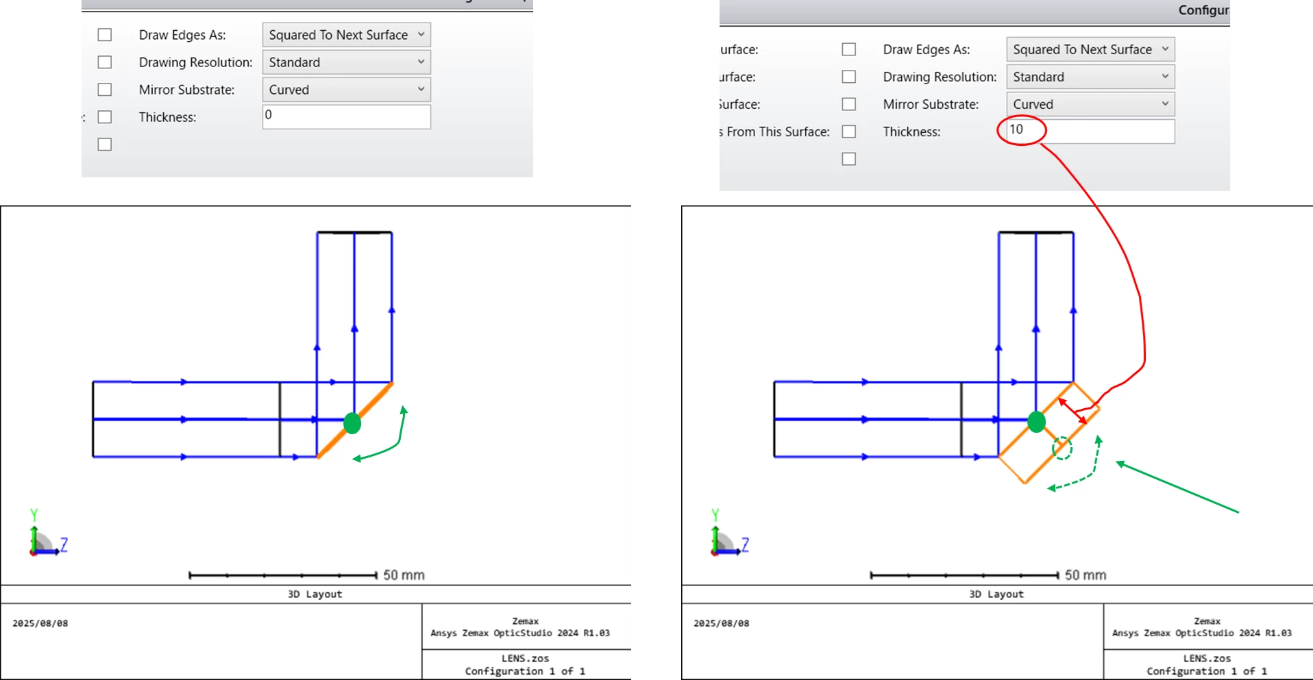
Here’s one way to do it. Insert a dummy surface ahead of the mirror and give it a thickness equal to the negative of the mirror thickness. The reference surface simply shows the pivot point. Disable “Hide X Bars” to see the center of the mirror, and how it pivots at the back. The only drawback is that the mirror aperture needs to change with tilt angle, and to be offset to keep it centered on the beam This would all be better done with a ZPL solve.
Here’s one way to do it. Insert a dummy surface ahead of the mirror and give it a thickness equal to the negative of the mirror thickness. The reference surface simply shows the pivot point. Disable “Hide X Bars” to see the center of the mirror, and how it pivots at the back. The only drawback is that the mirror aperture needs to change with tilt angle, and to be offset to keep it centered on the beam This would all be better done with a ZPL solve.
Mike
Hi Mike
Thank you for your reply. I will give it a try and also consider other methods.
I would use the 2 built-in tools to the Lens Data Editor:
Add Fold Mirror
Tilt/Decenter Elements
The Add Fold Mirror will properly convert all thicknesses and radii to the proper sign convention while the Tilt/Decenter Elements tool has a relatively new feature of “Pivot About Point”. Make the First Surface and Last Surface your mirror element and then make Pivot Z the thickness of your substrate:
Hi Mike
thanks for your advice
as far as my understanding, it seems this method is similar to the link below
Regarding this issue, I am trying to better understand the coordinate break.
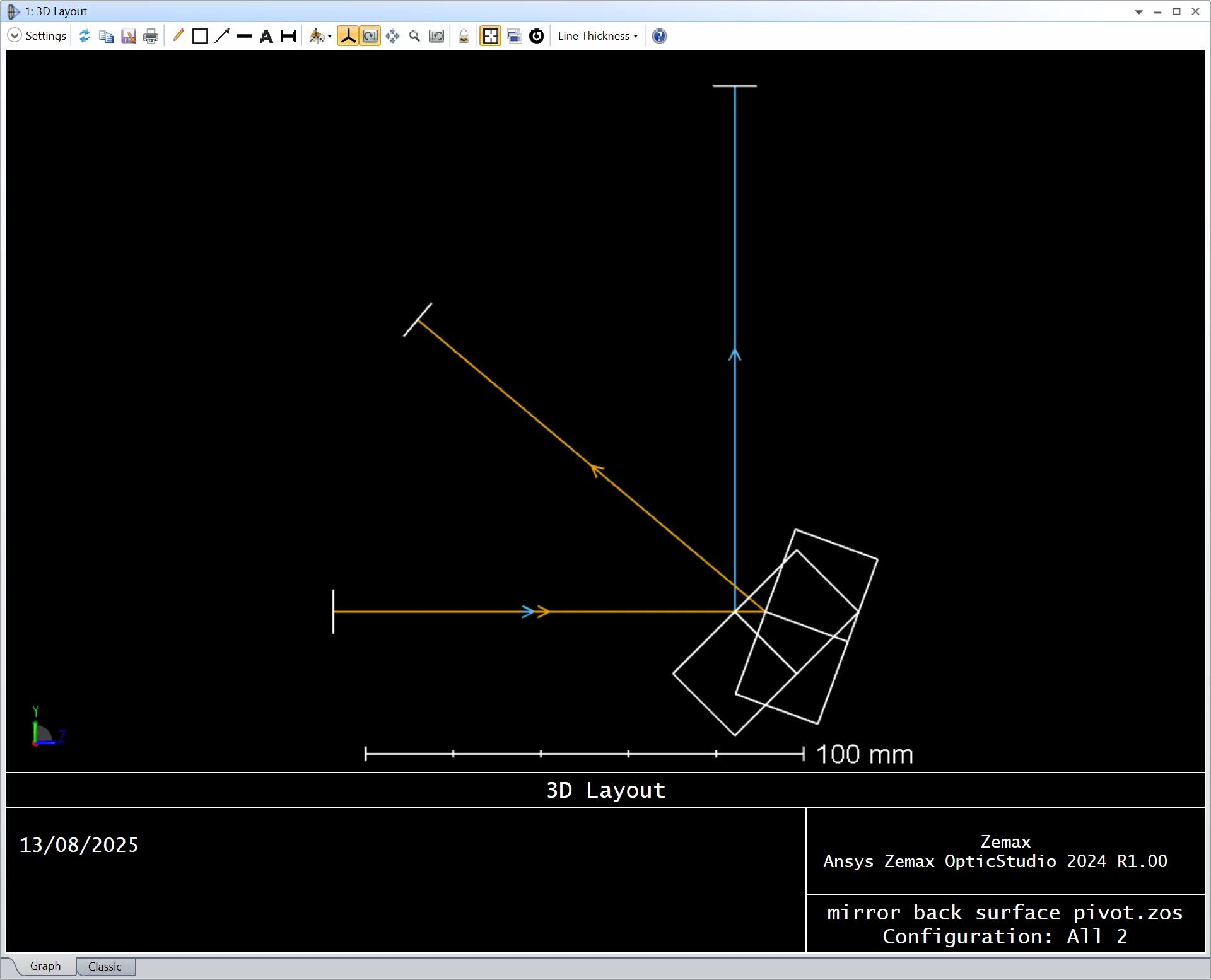
Attached is my attempt and current understanding of the coordinate break/coordinate system in Zemax. I would really appreciate it if you could point out any misunderstandings.
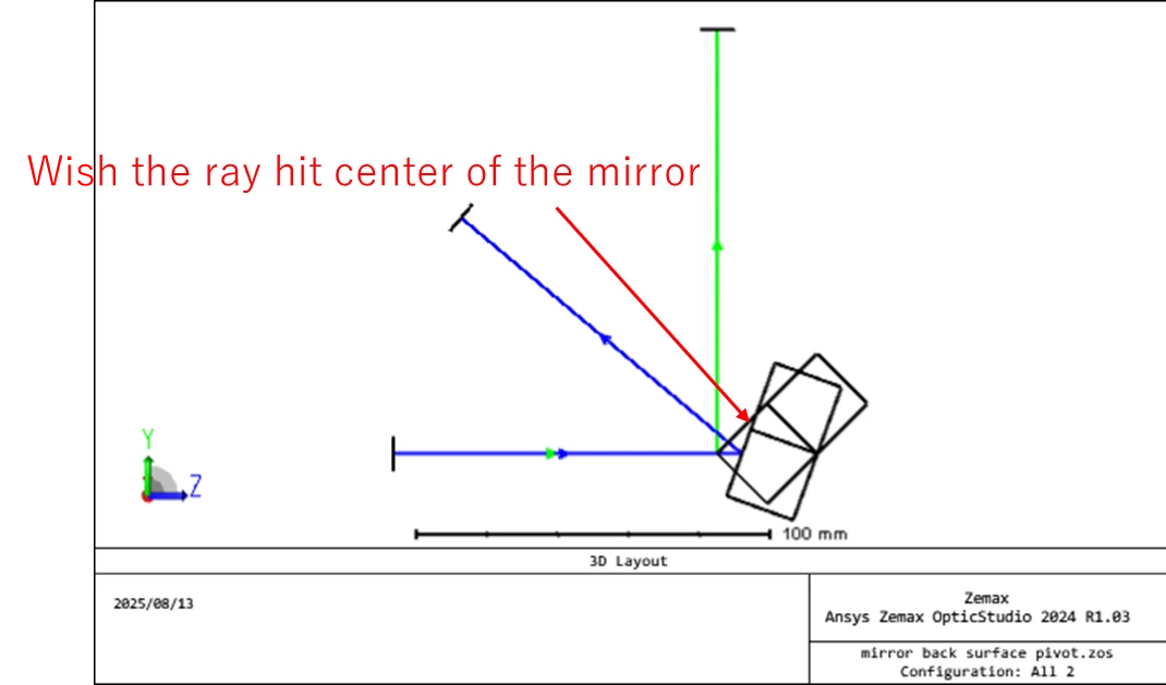
Also, while the back surface of the mirror seems to be working well, I’ve encountered a new issue — the chief ray only hits the center of the mirror surface.
Do you have any suggestions on how to resolve this? I tried using the chief ray solution in decenter Y , but it didn’t work.
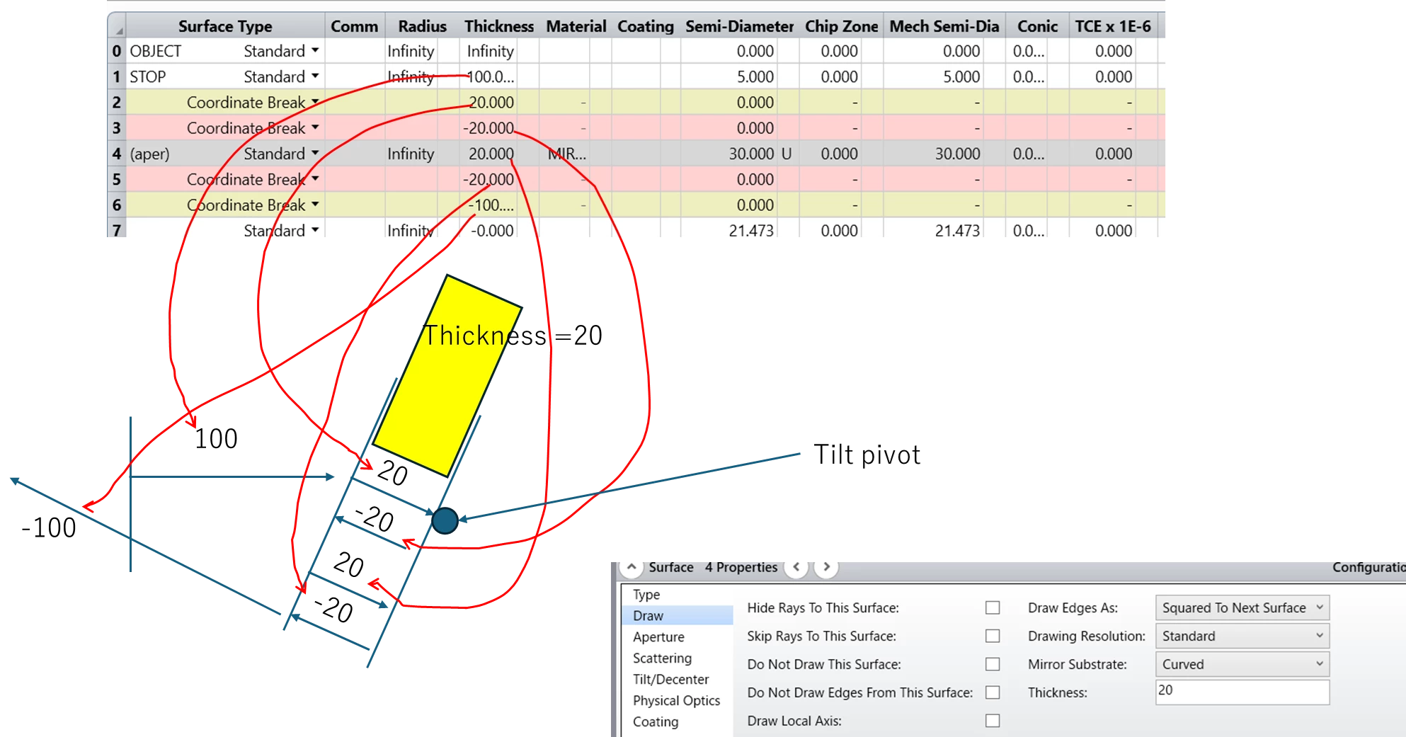
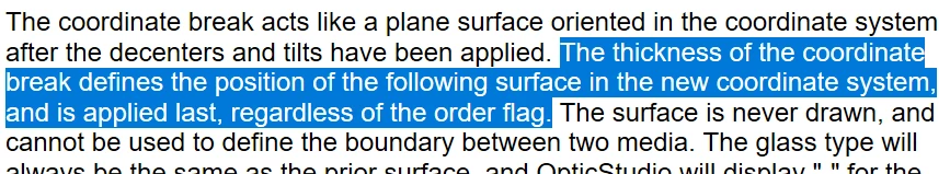
Regarding your first drawing, there might be a slight mistake. Although the Thickness column is the first column to appear in the LDE (before Decenter and Tilt). It is actually applied last! See the following excerpt from the Help File (The Setup Tab » Editors Group (Setup Tab) » Lens Data Editor » Sequential Surfaces (lens data editor) » Coordinate Break)
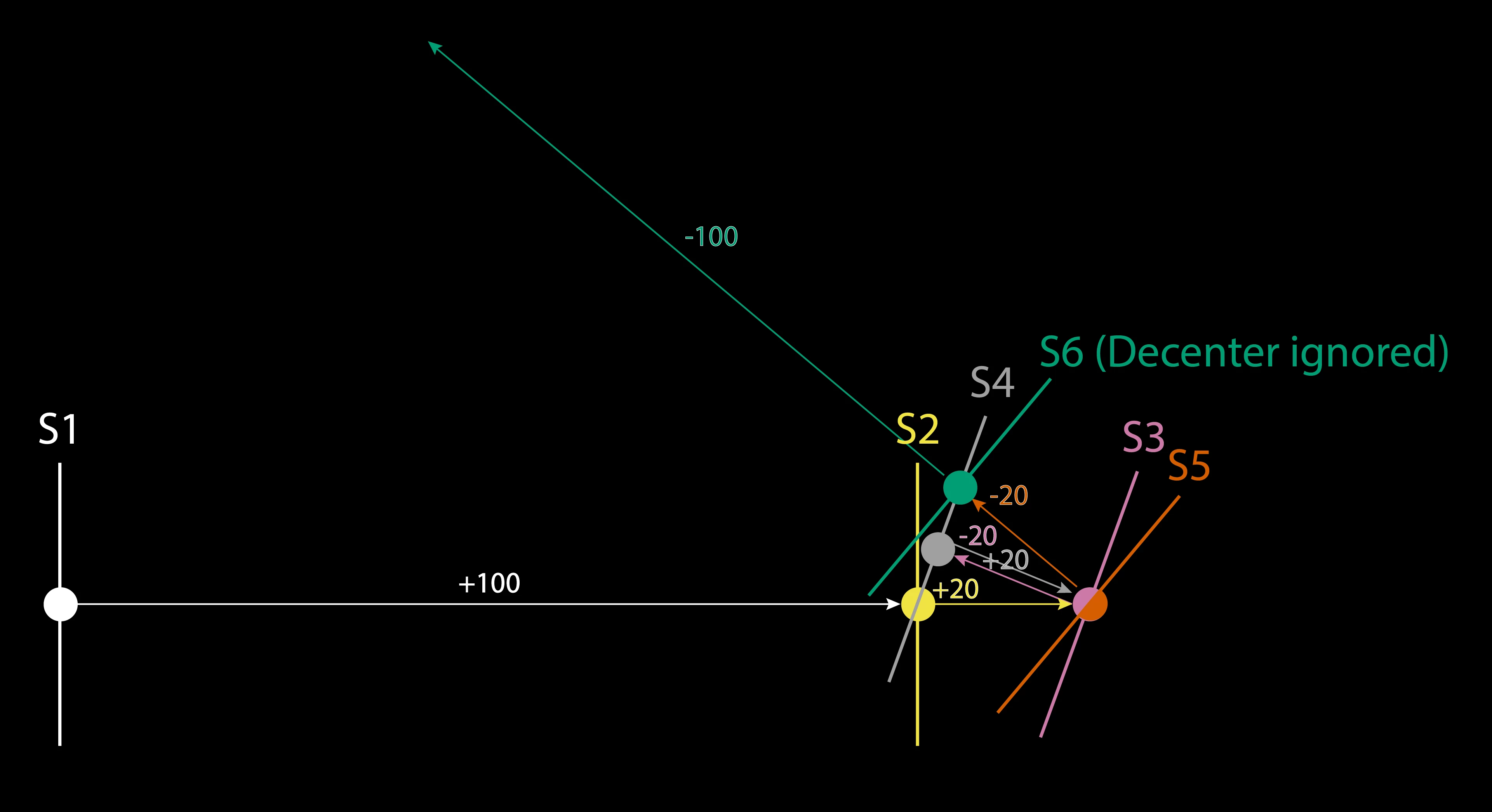
Also you seem to be missing the second rotation by 20 degrees on Surface 6.
Below you’ll find a figure of what I think is happening in your file. Note that I’m ignoring the Decenter Y on Surface 6 for simplicity. The arrows do not represent rays, instead they are here to indicated the Thickness like you have in your own drawing.
I’m also writing a “pseudo propagation logic” for clarity:
From S1 place S2 +100 units away along Z
From S2 place S3 +20 units away along Z
Rotate S3 by +20 degrees
From S3 place S4 -20 units away along Z’ (tilted by +20 degrees)
From S4 place S5 +20 units away along Z’ (tilted by +20 degrees) - Effectively going back to S3
Rotate S5 by +20 degrees
From S5 place S6 -20 units away along Z’’ (tilted by +40 degrees)
From S6 place S7 (not shown) -100 units away along Z’’ (tilted by +40 degrees)
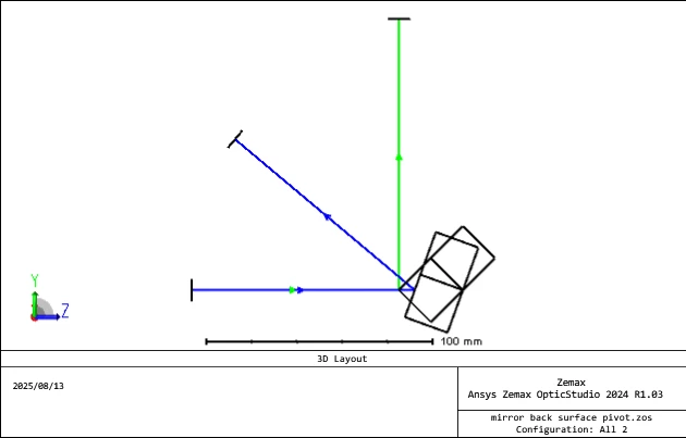
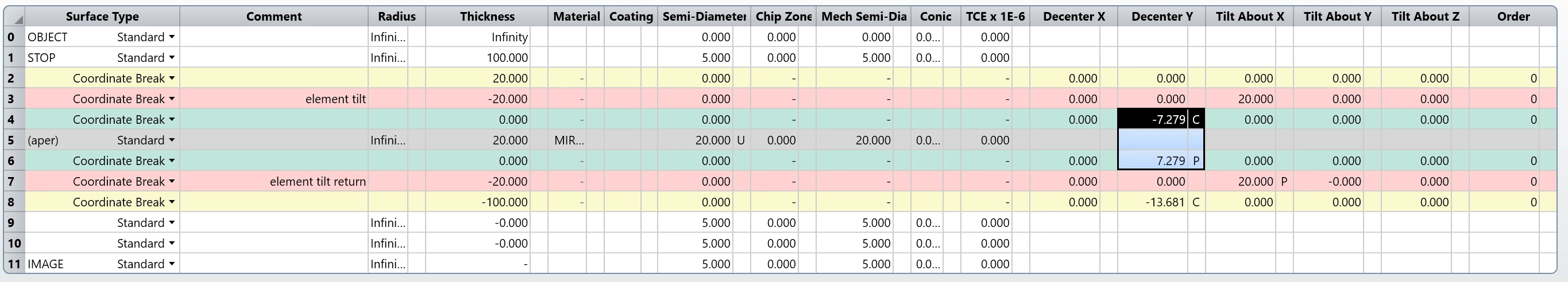
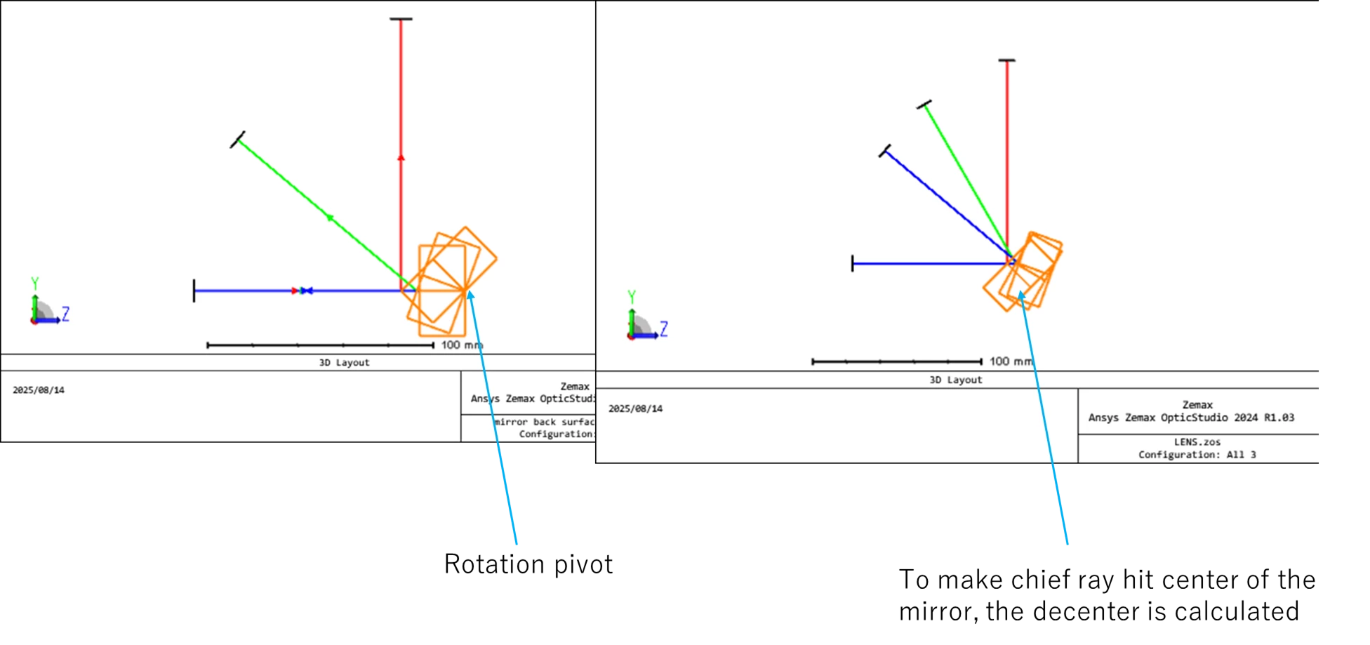
I’m not really sure what you are trying to achieve, but you could add another set of Coordinate Breaks around the Mirror surface and have a Chief Ray Solve (and its corresponding return to keep the pivot point) like so:
That way, the Mirror is rotated around its back face vertex while having the chief ray hit the center of the front face.
Regarding your first drawing, there might be a slight mistake. Although the Thickness column is the first column to appear in the LDE (before Decenter and Tilt). It is actually applied last! See the following excerpt from the Help File (The Setup Tab » Editors Group (Setup Tab) » Lens Data Editor » Sequential Surfaces (lens data editor) » Coordinate Break)
Also you seem to be missing the second rotation by 20 degrees on Surface 6.
Below you’ll find a figure of what I think is happening in your file. Note that I’m ignoring the Decenter Y on Surface 6 for simplicity. The arrows do not represent rays, instead they are here to indicated the Thickness like you have in your own drawing.
I’m also writing a “pseudo propagation logic” for clarity:
From S1 place S2 +100 units away along Z
From S2 place S3 +20 units away along Z
Rotate S3 by +20 degrees
From S3 place S4 -20 units away along Z’ (tilted by +20 degrees)
From S4 place S5 +20 units away along Z’ (tilted by +20 degrees) - Effectively going back to S3
Rotate S5 by +20 degrees
From S5 place S6 -20 units away along Z’’ (tilted by +40 degrees)
From S6 place S7 (not shown) -100 units away along Z’’ (tilted by +40 degrees)
I’m not really sure what you are trying to achieve, but you could add another set of Coordinate Breaks around the Mirror surface and have a Chief Ray Solve (and its corresponding return to keep the pivot point) like so:
That way, the Mirror is rotated around its back face vertex while having the chief ray hit the center of the front face.
Let me know if that helps and take care,
David
Hi David,
Thanks for your reply!
Reading your explain, I found I have made a mistake. Actually, I want to achieve
mirror rotate at the pivot of its back surface
the chief ray always hit the center of the mirror front surface
Reading your explain, I found I have made a mistake. Actually, I want to achieve
mirror rotate at the pivot of its back surface
the chief ray always hit the center of the mirror front surface
at the same time.
AND it is impossible… =============
Hi Yang,
I think that what you describe IS impossible, genuinely, and is not a limitation of the software.
The mirror is a solid body, and has a reflective front face and a back face that is used to position it. Thing of the vertices of the two surfaces. If the chief ray lands at 0 degrees incidence, it is aligned with the vertices of both faces. If you tilt the solid around the rear surface, the vertex of the front face must move up or down in y, depending on the angle of tilt. If the chief ray is still aligned with the vertex of the rear, because we set it up that way, it CANNOT be aligned with the vertex of the front at the same time. If the chief ray does not move, it MUST fit the front surface at some other point than the vertex.
I think the best way to model this, at least so you can get the motion that you have in your mind, is to do a quick experiment in non-sequential mode. Define three objects, in this order:
a source ray that points along (0, 0, 1) so it defines the z=0 axis
a NULL object
a Standard Lens object with its radii set in finite, and positioned relative to the NULL object 2
With the lens positioned relative to the NULL object, set up up so that the rear vertex of the lens of the lens is at (0,0,0) with respect to the null. Then tilt the NULL object, and observe the rigid body motion of the lens. You’ll see that the front face moves up or down such that the ray is no longer coincident with the front vertex.
If you want the ray to always be coincident with the front vertex, you can only tilt the lens about its front vertex. Any other tilt location will introduce a delta-Y.
In my opinion, 3D coordinate geometry is much easier to define in non-sequential mode, so build this experiment in NS mode and once you have it doing what you want it should be easier to define it sequentially. Please post the non-sequential model once it’s doing what you want if you need further advice on how to set it up sequentially.
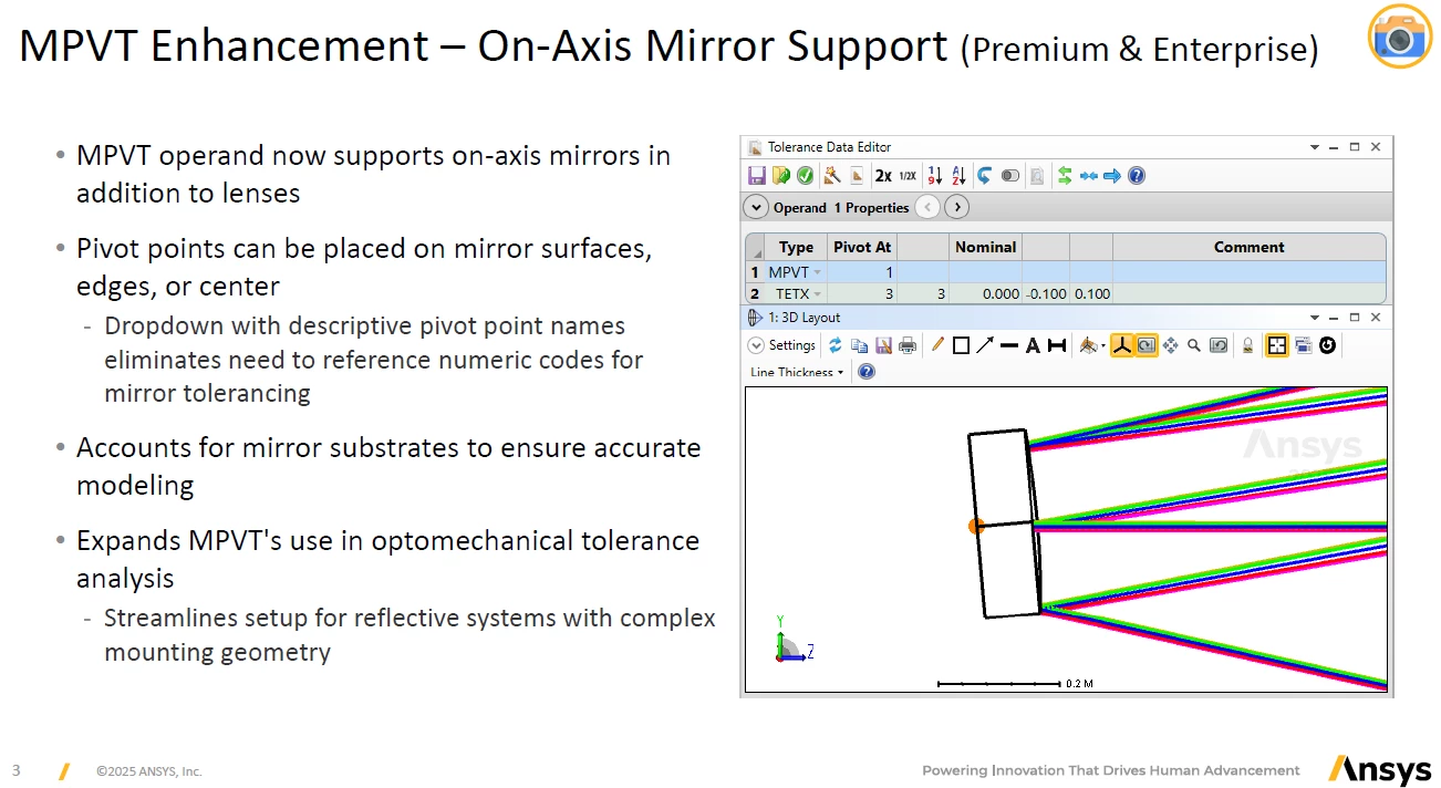
I just came across the new features in the 2025R2 version (unfortunately, they’re only available in Premium & Enterprise). It seems that setting the pivot on the back surface of the mirror has become easier.
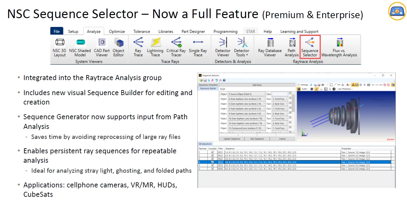
By the way, the feature below reminds me of the ray selection feature in LightTools.