Solved

How to best model thin films for fiber re-coupling?

  • 16 November 2023
  • 6 replies
  • 83 views

Userlevel 1
Badge

Hello,

I am currently simulating in zemax light recovery in an optical fiber in non-sequential mode. This fiber is in direct contact with a glass slide which has a complex thin-film coating on its surface. I am specifically trying to measure the spectrally modified signal that is re-coupled into the fiber. Using a macro, I’m able to sweep through all wavelengths and obtain the spectral signal by measuring at each wavelength the power re-coupled.

However, I know that the spectral response is highly angle-sensitive, and initial simulations show that moving the fiber away from the glass slide by distance less than the thickness of the coating changed the spectral response. Its fairly clear that the coating simulation in zemax does not account for any displacement of rays in the coating (which, admittedly, is OK for the vast majority of cases, but not for mine).

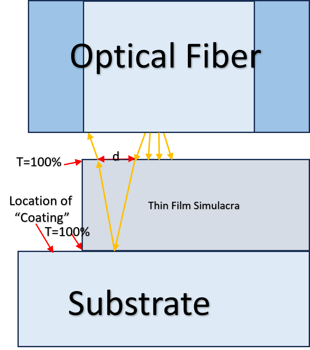
So, in a bid to have a more exact simulation, I’ve attempted to model displacement by creating a physical simulacra of the coating above the substrate. The “coating” aspect is simulated at the surface of the substrate, which each layer of the simulacra is considered to have a 100% transmittance. The simulacra displaces the rays, while each ray is affected a single time by the coating. An exceedingly small air gap (~100 nm) is left between the simulacra and the substrate to ensure the rays hit the coating at the same angle as they would normaly enter.

This remains a significant approximation. I’m essentially treating the wave-physics & ray-tracing parts of the simulation as separate. So as I havent found any extant examples of something similar, I have a few questions:

1) How to best approximate the displacement of rays within a coating?

2) Would any physical optics propagation tools function here? I am unexperienced with these tools, so I’m unsure. But I havent found any cases of POP being used to model thin films, so I’m doubtful.

2) How to best validate such approximations? (I am looking into getting some real coatings deposited for testing, but that does take time)

I know I’m doing something zemax was definitly not made for, but its the main tool I’ve got so I’m trying to get the most out of it.


icon

Best answer by Mark.Nicholson 29 November 2023, 19:25

View original

6 replies

Userlevel 1

1) How to best approximate the displacement of rays within a coating?

Your method seems a decent attempt for a non-sequential model. I would make your simulacra match your thin film stack with ideal AR coating between the layers. Then put the thin film stack on the substrate as you suggests.

I don’t think you should have an air gap if you don’t have one in the real world. But if you trying to account for the air gap from surface roughness you can keep it.

You also may want to look into the coherence length feature in non-sequential. It may give you better results.

2) Would any physical optics propagation tools function here? I am unexperienced with these tools, so I’m unsure. But I havent found any cases of POP being used to model thin films, so I’m doubtful.

I haven’t tried using coating with the POP. But it’s not designed for thin film modeling. 

2) How to best validate such approximations? (I am looking into getting some real coatings deposited for testing, but that does take time)

You can do this in FDTD and compare to the Ray trace method. By adjusting the ray trace to match the FDTD results you could get a tool that could do simulation faster than the FDTD which is computationally intensive. Ansys has a Lumerical tool that could likely handle this problem. 

Userlevel 1
Badge

1) How to best approximate the displacement of rays within a coating?

I don’t think you should have an air gap if you don’t have one in the real world. But if you trying to account for the air gap from surface roughness you can keep it.

You also may want to look into the coherence length feature in non-sequential. It may give you better results.

2) How to best validate such approximations? (I am looking into getting some real coatings deposited for testing, but that does take time)

You can do this in FDTD and compare to the Ray trace method. By adjusting the ray trace to match the FDTD results you could get a tool that could do simulation faster than the FDTD which is computationally intensive. Ansys has a Lumerical tool that could likely handle this problem. 

Thanks for the response!

For the air gap, there shouldn't be one between the thin film and its substrate. I’ll do some testing with/without to see what kind of difference it makes.

I’ll check the coherence length feature, though in my case its pretty short.

I’ll look into lumerical, though admittedly the learning curve for any new simulation software is pretty intimidating.

Userlevel 7
Badge +3

Hi @William Oak ,

Great use of the word ‘Simulacra’, BTW.

I wouldn’t worry about the displacement of the rays. You could not observe this in real life anyway. You really have to consider fields, rather than rays, when you model a thin-film coating. Rays are infinitely thin, so the split (displaced) rays would not interfere as they are not co-located. Instead, the ray is modeled as a piece of a plane wave, and we can coherently add all these multiply-reflected fields to give the reflection, transmission, phase etc that the ray ‘would’ see if you actually could make a ray in real life :-) See the section of the Help under The Setup Tab > System Group (the Setup Tab) > System Explorer > Polarization (System Explorer) > Review of Polarization Concepts > Field vs. Ray Phase Conventions for more details.

The response of thin film coatings is highly angle (and wavelength) sensitive but that all comes out of the math used for modeling the coatings. I don’t really see any reason why your case is different to any other coating simulation, TBH. Ray tracing itself is only a valid representation of light when the components are of the order of a few wavelengths in any case. After that, you need to use something like Lumerical’s codes when you are concerned about wave guiding by the structure, rather than simple ray bending at interfaces.

By all means investigate Lumerical’s offerings, but IMHO you’d need that to model the propagation inside the fiber, where the light is being guided. In free space propagation (including thin-films) the ray tracing approach should be fine.

  • Mark


Userlevel 1
Badge

Hi @William Oak ,

I wouldn’t worry about the displacement of the rays. You could not observe this in real life anyway. You really have to consider fields, rather than rays, when you model a thin-film coating. Rays are infinitely thin, so the split (displaced) rays would not interfere as they are not co-located. Instead, the ray is modeled as a piece of a plane wave, and we can coherently add all these multiple-reflected fields to give the reflection, transmission, phase etc that the ray ‘would’ see if you actually could make a ray in real life :-) See the section of the Help under The Setup Tab > System Group (the Setup Tab) > System Explorer > Polarization (System Explorer) > Review of Polarization Concepts > Field vs. Ray Phase Conventions for more details.​​​​

Thanks for the feedback! I’m glad to have some insight on how zemax manages thin film simulation.

If I’m understanding you properly, the thin film simulator likely wouldn’t be accurate when considering non-collimated light? I guess my doubts are around how the waves interact when you have rays at different angles entering the same medium, and how that “wave” would exit the coating. My own approach for the re-coupling has simply been using a detector with the right spot size/angular acceptance as the fiber , so I know I’m simplifying somewhat.

I’ll definitely spend some time in the help to get a better grasp of things.


Userlevel 7
Badge +3

Hi William,

The thin-film code is accurate irrespective of whether the light is collimated, diverging, converging, in a caustic, whatever. It operates on individual rays, not bundles, so it has no idea what is going on at the system level.

There’s probably some good articles in the Knowledge Base to help with understanding this

  • Mark
Userlevel 1

Zemax uses a transfer matrix method to model the coating. The treatment can handle rays coming in at any angle. It’s a very robust technique as longs as you can approximate the layers as infinity large plane slabs. 

See the link for a introduction to the method. 

https://en.wikipedia.org/wiki/Transfer-matrix_method_(optics)

Reply