Hello,
I am currently trying to understand the sampling behavior of the FFT PSF analysis in OpticStudio. The analysis has two sampling parameters:
- ‘Sampling’, hereafter referred to as S, documented as “The size of the ray grid used to sample the pupil”.
- ‘Display’, hereafter referred to as D, documented as “The display size indicates what portion of the computed data will be drawn when a graphic display is generated. The display grid can be any size from 32 x 32 up to twice the sampling grid size. Smaller display sizes will show less data, but at higher magnification for better visibility”.
Based on implementations described in the literature and basic tests with OpticStudio, I assumed the PSF calculation works like this:
- Sample the wavefront at the pupil with a sampling S;
- Zero-pad the wavefront to the maximum possible display sampling Dmax;
- Crop the result to a size D. This last step was inferred from OpticStudio’s output.
Based on the properties of the Fourier transform, I assume the following behavior when changing the sampling parameters:
- Increasing the pupil sampling S increases the extent of the PSF. For example, if the extent of the PSF is 10 μm with S = 32x32, it will double to 20 μm when S is doubled to 64x64.
- Increasing the display sampling D while keeping S the same will increase the PSF resolution, i.e. the spacing dx between two adjacent points in the PSF will decrease.
In OpticStudio, the PSF resolution depends on the ratio D / S. D has to be in the range [S, 2S] and choosing D < 2S appears to crop or zoom the PSF, so OpticStudio does not allow to adjust the ratio D / S. As a result, assumption 2 cannot be tested by increasing D, but we can test assumption 1. I performed this test on the ‘Cooke 40 degree field’ sample.
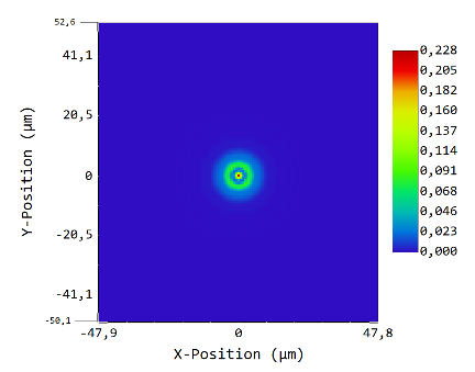
Let’s start with S = 64x64, D = 128x128:

dx = 0.818 μm, data area is 104.759 μm wide.
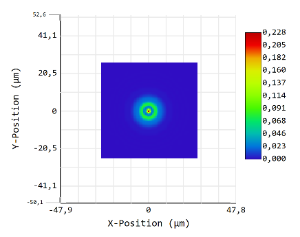
Now decrease D to 64x64:

This indeed only crops the PSF. dx remains the same.
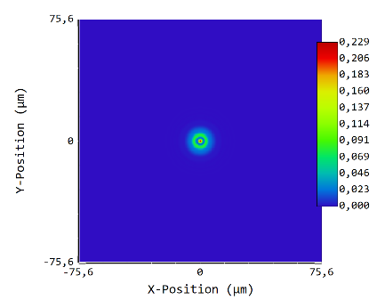
Now increase S to 128x128 and D to 256x256. D / S remains the same, so the extent should not change, but S is doubled, so dx should be halved. Result:

dx = 0.588 μm, data area is 150.541 μm wide. dx is not halved, so assumption 1 is not true; furthermore, the PSF extent changed, so assumption 2 is also not true.
I think this means I wrongly assumed D is the size of the grid over which the PSF is calculated. My question is: how, then, does OpticStudio choose the size of the grid over which the PSF is calculated, and (how) does this relate to the ‘Display’ sampling D?
I see a few options:
- OpticStudio has a hardcoded relation between the pupil sampling S and the PSF grid size D’. It then finds the bounds where the PSF becomes almost zero, crops it to these bounds, and resamples the result to the display grid size D.
- OpticStudio somehow calculates which PSF grid size D’ to use such that the PSF reaches 0 at a grid size of 2S. It then crops the PSF to the selected display grid size D, without resampling. I expect this to be inefficient because it may require multiple PSF calculations, but maybe there’s a smart way to predict the required value of D’ without calculating the PSF twice.
Curious to hear if anybody here knows how this works!


