Hello! Does anybody know how total internal reflection (TIR) is handled in geometric image analysis?
Thanks!
Liz
Hello! Does anybody know how total internal reflection (TIR) is handled in geometric image analysis?
Thanks!
Liz
Best answer by Jeff.Wilde
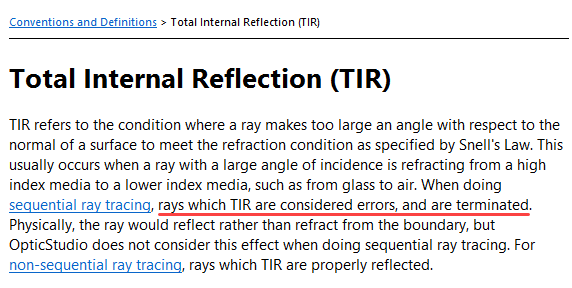
Just to add to Michael’s response, the help documentation summarizes how TIR rays are handled:
Regarding the vignetting issue, here are some more details and examples that may be helpful.
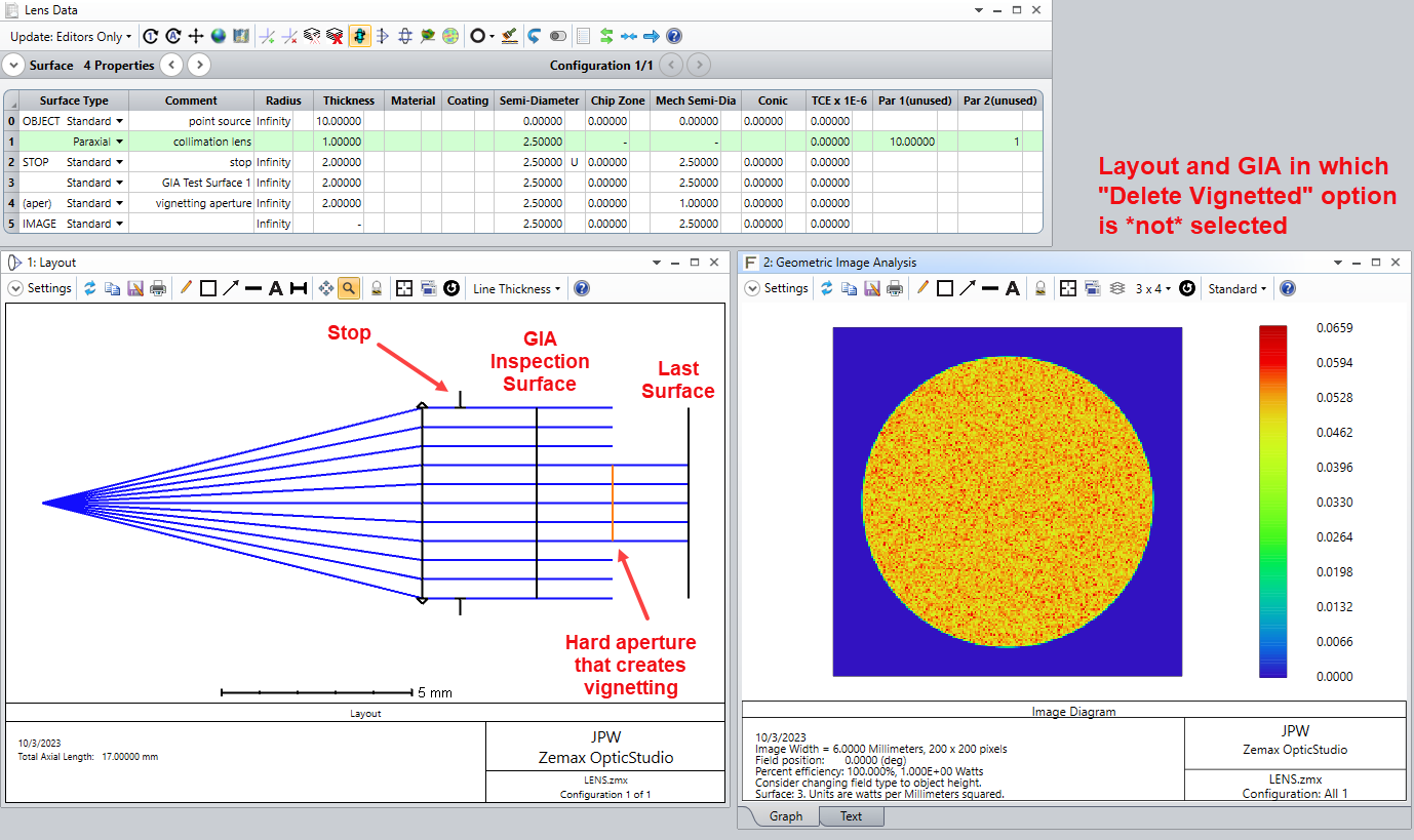
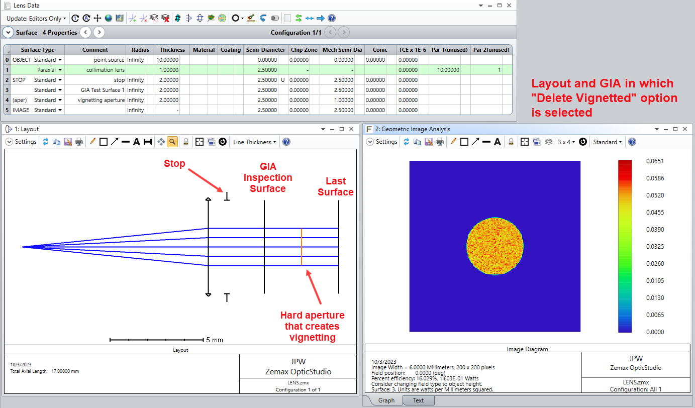
Vignetting in sequential mode occurs because of an aperture (or possibly TIR) on some surface, other than the stop surface, that blocks rays from reaching the last surface. When using the GIA tool to view the ray distribution at a surface following the vignetting surface, the rays that are blocked by the aperture (or terminated by TIR) on the vignetting surface will not appear because they have already been terminated.
However, there may be occasions when the user is interested in viewing the ray distribution at a plane that proceeds the vignetting surface. Then the question arises, would you like to see all of the rays crossing that surface or only the subset of rays that were ultimately able to pass through the downstream aperture (or that did not suffer TIR) and make it to the final surface? Why would someone be interested in the latter case? Well, the case of TIR is a prime example. Even though the rays exist at surfaces prior to a TIR surface, you might only care about the spatial distribution of those rays that do not subsequently suffer TIR, and would like to see their distribution at a plane before reaching the TIR surface. There are many other examples too, so it’s very useful to have the “Delete Vignetted” option for these intermediate surfaces.
Here is one simple example that illustrates the two options when the GIA tool displays the image at an intermediate surface in front of a hard aperture:
Delete Vignetted is not selected
Delete Vignetted is selected
Here is a second example that shows similar behavior for TIR from a prism surface.
First, let’s set the refractive index of the prism to 1.0 so that there is no TIR.
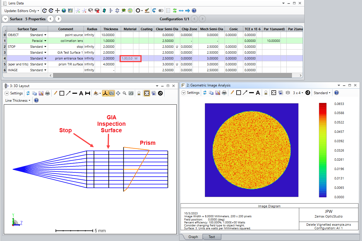
Now, let’s set the prism index to 3.0 so that TIR occurs, but we will look at the ray distribution before TIR without using the “Delete Vignetted” option.
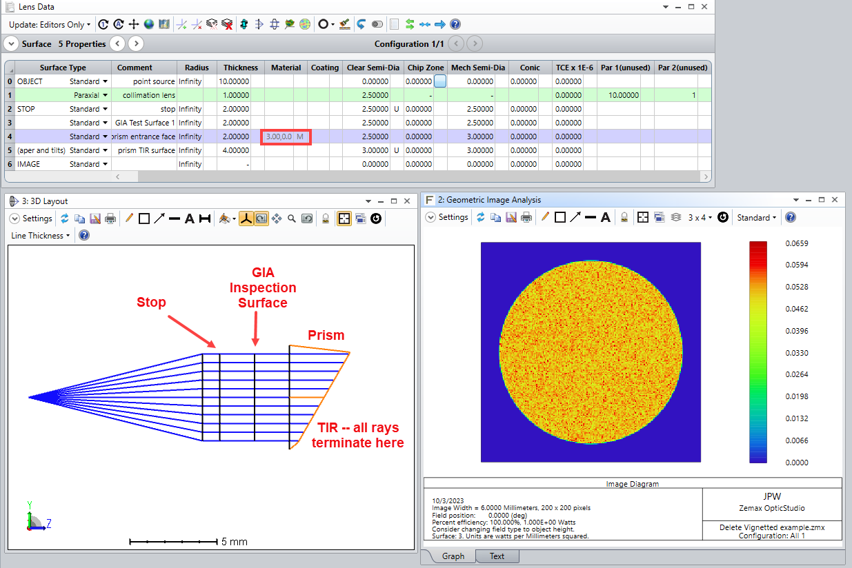
Now, let’s select the Delete Vignetted option for both the layout and GIA windows -- in this case no rays are shown because of the TIR condition.
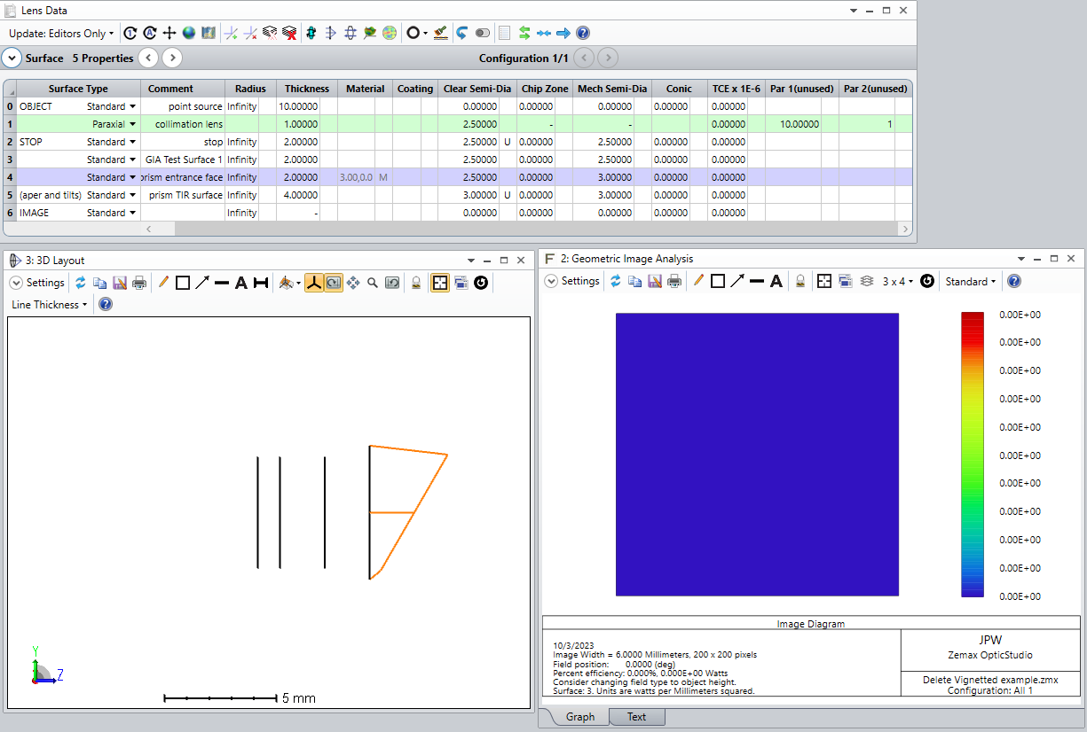
Hope this helps...
Regards,
Jeff
Enter your E-mail address. We'll send you an e-mail with instructions to reset your password.