I’m trying to design beam homogenizer and checking several concepts: rectangular rod and fly’s eye lens.
In my case the source is quite large, 10.4x7.5mm.
I looked at Zemax sample file: Digital_projector_flys_eye_homogenizer.zmx.
The source size is 0.25x0.25mm. Up to about 1x1mm the design works good. Increasing source size decrease the beam parallelism hitting the fly’s eye which reduce dramatically performance.
Do you know if this concept can work with larger source as in my case: 10.4x7.5mm.
s quite large, 10.4x7.5mm.
I looked at Zemax sample file: Digital_projector_flys_eye_homogenizer.zmx.
The source size is 0.25x0.25mm. Up to about 1x1mm the design works good. Increasing source size decrease the beam parallelism hitting the fly’s eye which reduce dramatically performance.
Do you know if this concept can work with larger source as in my case: 10.4x7.5mm.
Best answer by David
Hello,
This is an interesting problem.
The design of fly’s eye homogenizers is very dependent on the source being homogenized. It would be very unusual to find that a design for one source worked for another, unless they were very similar. And the lens arrays are molded. They are low cost in high volumes, but for low volumes the tooling cost is amortized over a smaller number of items, which can lead to very high per-item costs. This led me to first look at a rod homogenizer. I did achieve what I think is a reasonable design. But the file I saved yesterday won’t open today. I sent it to support. Maybe they can find the issue. If not, I’ll recreate it. I think it is likely the best alternative.
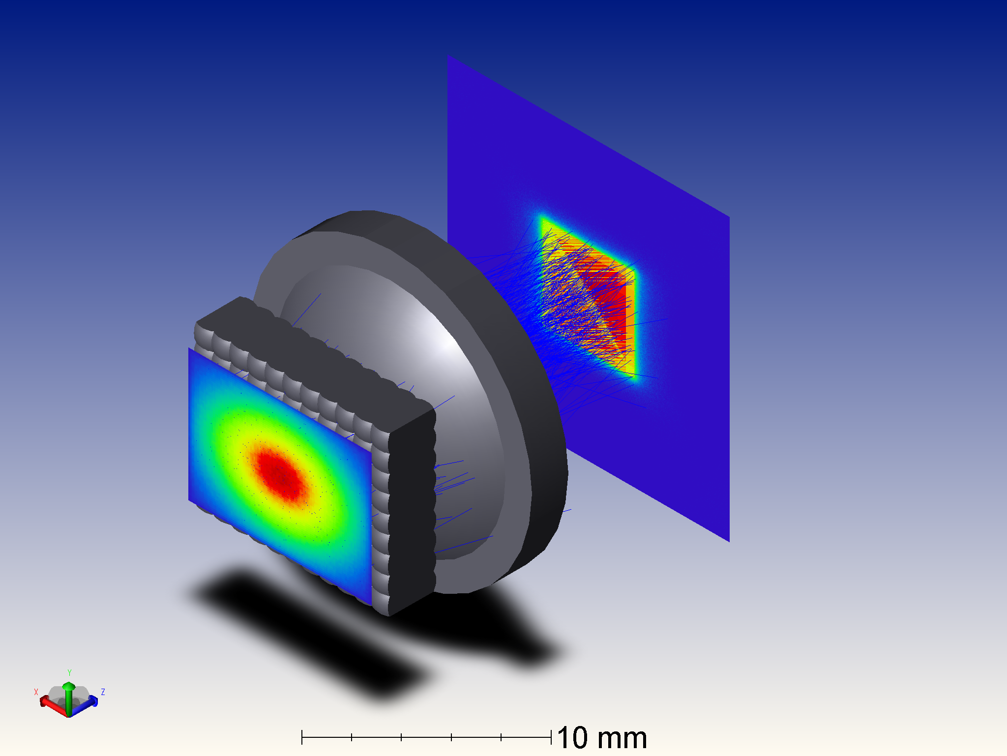
My experience with flies-eye homogenizers is similar to the example you reference. The beam sent through the lens arrays has been formed into a wide beam with low divergence. This means the objective and field array can be well separated and the speed of the objective lenslets will be modest. In this case, with a divergence angle of 15 degrees and lenslets likely about 1mm on a side, the spacing will be close, and the objective lenses need to be faster.
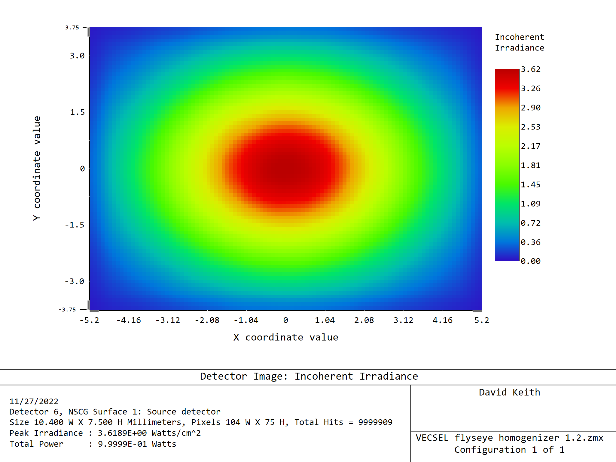
Not knowing more about it. I modeled the source as Source Diode with a Gaussian divergence with 1/e^2 at 15 degrees. To introduce nonuniformity, I modeled it has having a Gaussian spatial distribution with the 1/e^2 points at the edges of the 10.4x7.5 rectangle. The source could be made more hard-edged with supergaussian values other than 1. The entire design is dependent on the source, so the result might not be valid without adjustment.
In the attached file, you will see a number of sources. One of them models the VECSEL output (maybe); the rest are used at various points in the design process.
A Source Ray at 15 degrees is used to graphically determine the array spacing. (An easy trig problem as well.)
A Source Two Angle is used together with a detector to optimize the central objective lenslet to image onto the central field lenslet.
Another Source Two Angle is used to optimize the central field lenslet to image the central objective lenslet onto a plane on which the group of light bodies is formed.
These sources are also used to optimize the condenser lens to merge off axis light bodies onto the central location.
In a final optimization, the condenser lens is optimized to maximize power in the final 5mmx5mm light body. Preventing TIR in the condenser is challenging.
The merit function for this work are created as needed using the wizard.
The spacing between the lens arrays is so small that they are formed on two sides of a single plate. The plate is made of L-BAL35 which is a moldable glass with good transmission in the visible and SWIR. The condenser is also L-BAL35.
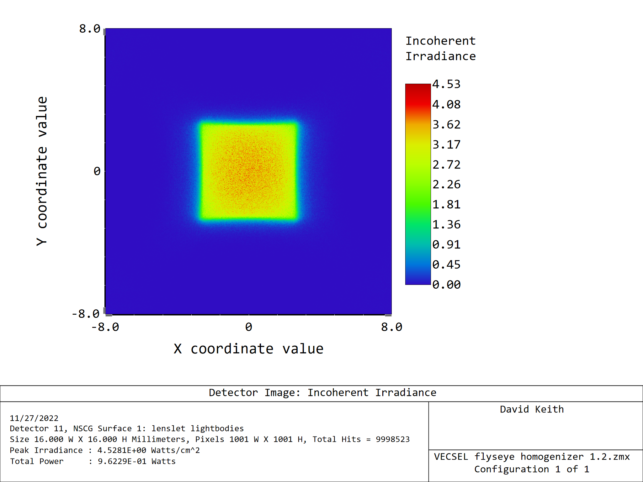
The resulting lightbody is reasonably well defined, but could be better.
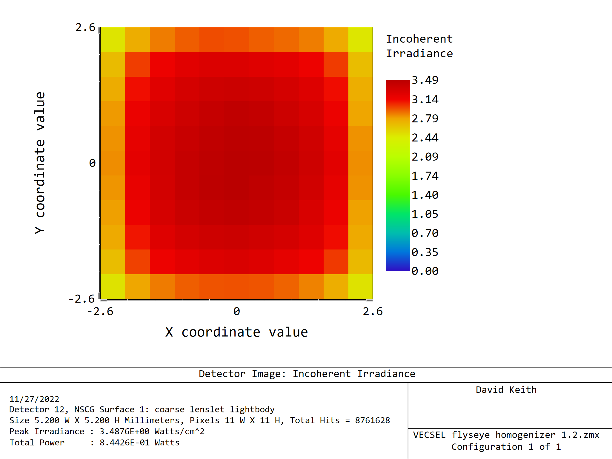
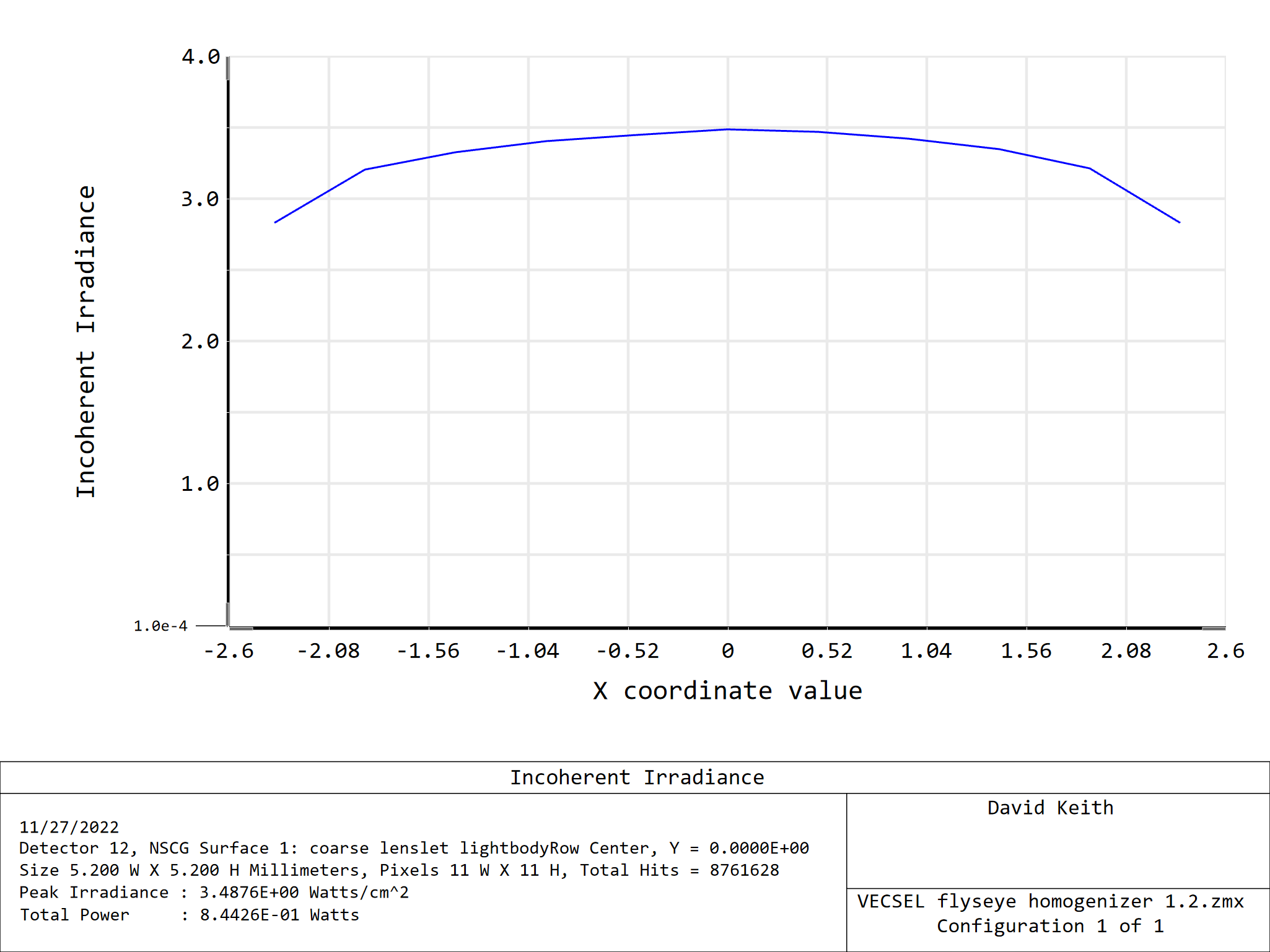
A 5.2 x 5.2 mm core contains 84% of the source power. The uniformity could be better.
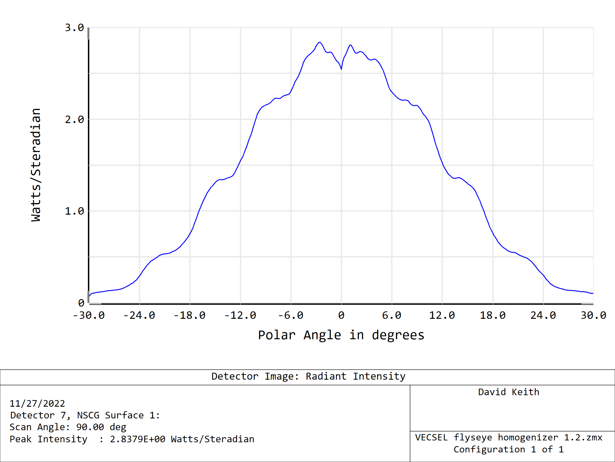
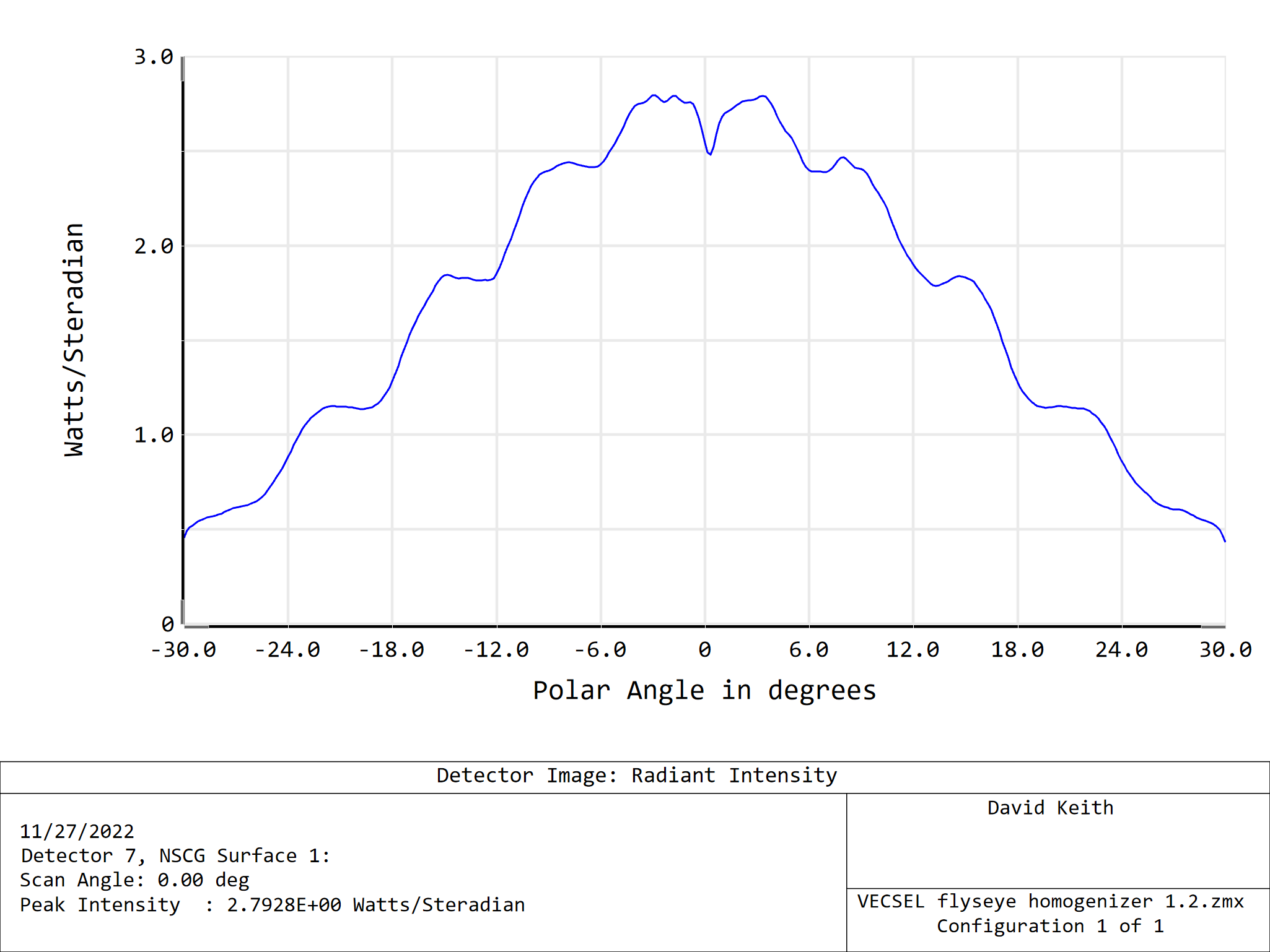
The angular distribution is not as tight as specified. This could likely be improved by redesigning for a larger light body.
This axis is not bad:
But this one is worse:
I have attached the ZMX file in a Zip. Unfortunately, I could not include a ZAR file because it is 200MB in size. The limit for uploading is 5MB, which seems a but low in this day and age.
This design could likely be improved, but I did not want to go any farther without a good spec for the VECSEL output.
it would help to know more about the source and your requirements. What is the angular divergence of the source? If you are trying to form a light body, what size does it need to be, and for it what divergence angle is permissible?
There are limits to what can be achieved due to conservation of etendue. Depending on these answers, it might be that a lower intensity source of smaller size and/or less divergence would produce more usable output.
The source is telecentric with half angle cone of 15deg (Vecsel).The beam shape can be from 5x5 to 8x8mm, half cone can be up to 20 deg. I am aware to conservation of etendue and that lower beam shape will increase angular beam size. Efficiency should be better than 80%.
The design of fly’s eye homogenizers is very dependent on the source being homogenized. It would be very unusual to find that a design for one source worked for another, unless they were very similar. And the lens arrays are molded. They are low cost in high volumes, but for low volumes the tooling cost is amortized over a smaller number of items, which can lead to very high per-item costs. This led me to first look at a rod homogenizer. I did achieve what I think is a reasonable design. But the file I saved yesterday won’t open today. I sent it to support. Maybe they can find the issue. If not, I’ll recreate it. I think it is likely the best alternative.
My experience with flies-eye homogenizers is similar to the example you reference. The beam sent through the lens arrays has been formed into a wide beam with low divergence. This means the objective and field array can be well separated and the speed of the objective lenslets will be modest. In this case, with a divergence angle of 15 degrees and lenslets likely about 1mm on a side, the spacing will be close, and the objective lenses need to be faster.
Not knowing more about it. I modeled the source as Source Diode with a Gaussian divergence with 1/e^2 at 15 degrees. To introduce nonuniformity, I modeled it has having a Gaussian spatial distribution with the 1/e^2 points at the edges of the 10.4x7.5 rectangle. The source could be made more hard-edged with supergaussian values other than 1. The entire design is dependent on the source, so the result might not be valid without adjustment.
In the attached file, you will see a number of sources. One of them models the VECSEL output (maybe); the rest are used at various points in the design process.
A Source Ray at 15 degrees is used to graphically determine the array spacing. (An easy trig problem as well.)
A Source Two Angle is used together with a detector to optimize the central objective lenslet to image onto the central field lenslet.
Another Source Two Angle is used to optimize the central field lenslet to image the central objective lenslet onto a plane on which the group of light bodies is formed.
These sources are also used to optimize the condenser lens to merge off axis light bodies onto the central location.
In a final optimization, the condenser lens is optimized to maximize power in the final 5mmx5mm light body. Preventing TIR in the condenser is challenging.
The merit function for this work are created as needed using the wizard.
The spacing between the lens arrays is so small that they are formed on two sides of a single plate. The plate is made of L-BAL35 which is a moldable glass with good transmission in the visible and SWIR. The condenser is also L-BAL35.
The resulting lightbody is reasonably well defined, but could be better.
A 5.2 x 5.2 mm core contains 84% of the source power. The uniformity could be better.
The angular distribution is not as tight as specified. This could likely be improved by redesigning for a larger light body.
This axis is not bad:
But this one is worse:
I have attached the ZMX file in a Zip. Unfortunately, I could not include a ZAR file because it is 200MB in size. The limit for uploading is 5MB, which seems a but low in this day and age.
This design could likely be improved, but I did not want to go any farther without a good spec for the VECSEL output.
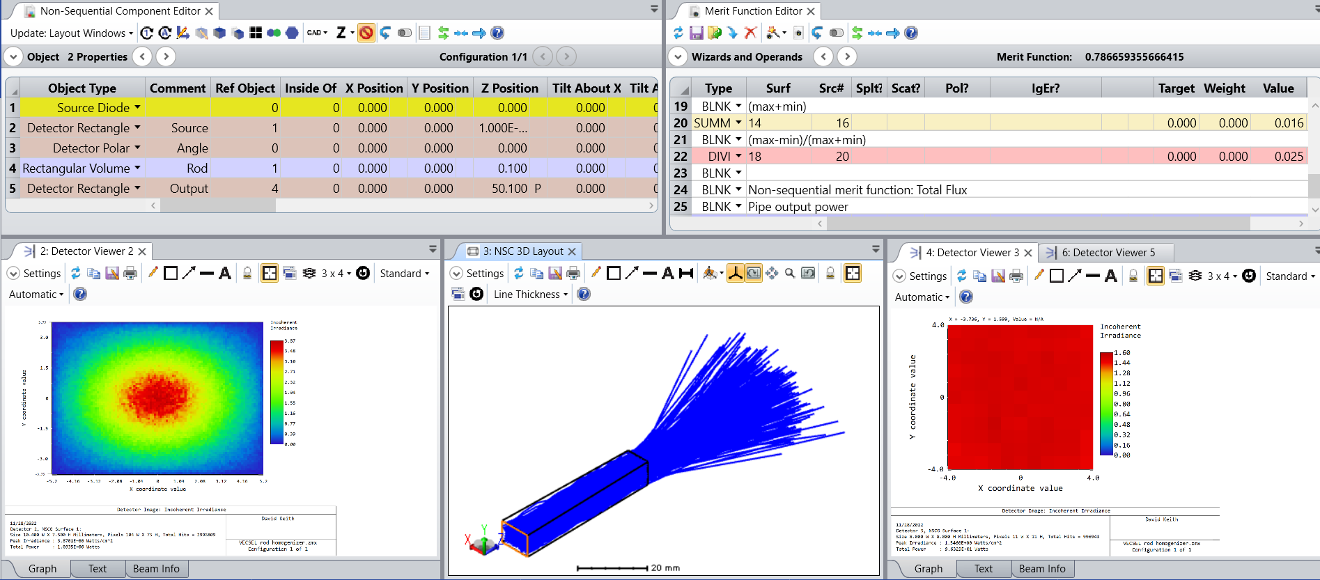
After updating OS, I managed to open the rod homogenizer.
The source is modeled as in the fly’s eye. The homogenizer is a fused silica rod. The input face has the dimensions of the source. The output face is 8x8mm.
The output of the pipe is 96% of the input. (There is AR on the input and output faces.) The missing 4% has been TIR off the exit face and sent back through the rod to the source. Depending on the application, an isolator might be needed to protect the source. Nonuniformity at the output is measured with an 11x11 pixel detector. By (max-min)/(max+min) nonuniformity is 1.5% with 1E7 rays traced. Divergence of the output is within 20 degrees.