
Hi there friends from the OpticStudio community,

Today I have a question related to a general optics design problem.

I’m trying to generate a system similar to what is presented in the following publication:

https://opg.optica.org/ol/fulltext.cfm?uri=ol-42-6-1043&id=360492

In essence, the design problem consists of generating a high NA system which can be used to image molecules or atoms in a vacuum environment. 

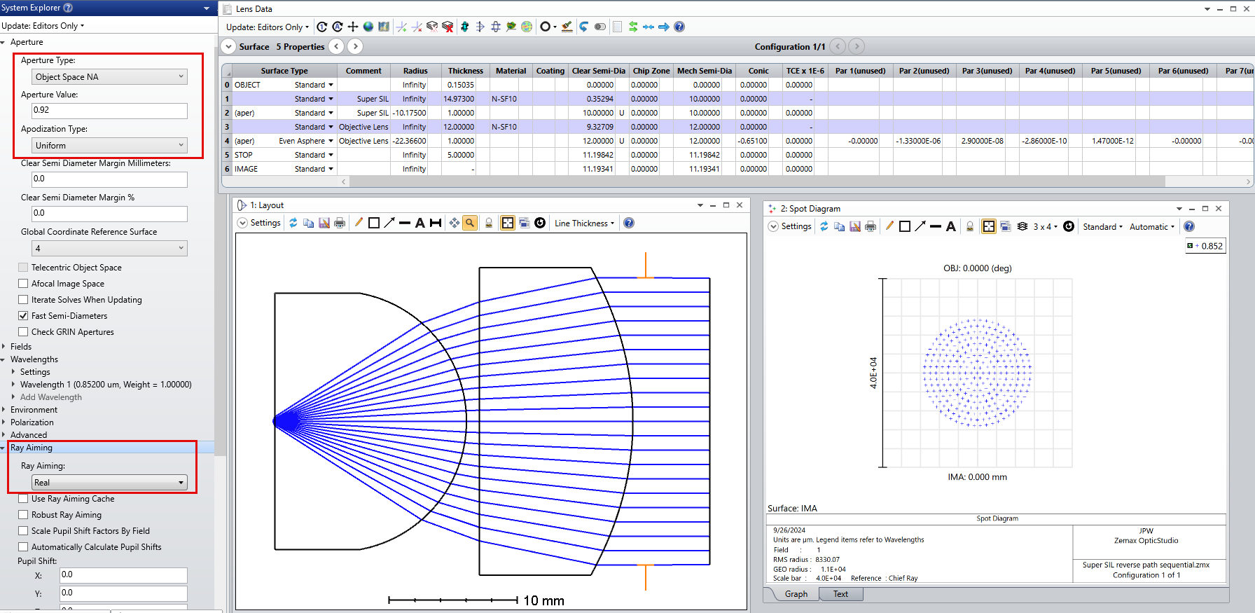
The approach used in this case consists of using a Weierstrass type solid immersion lens in combination with two aspherical surfaces in order to generate a collimated beam for an on axis point object.

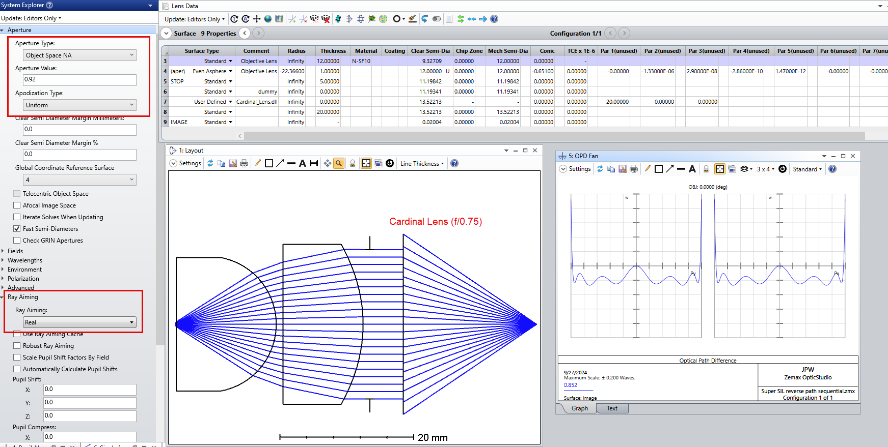
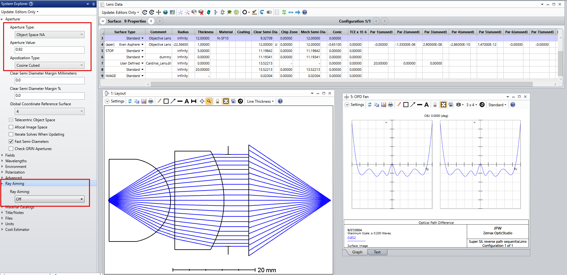
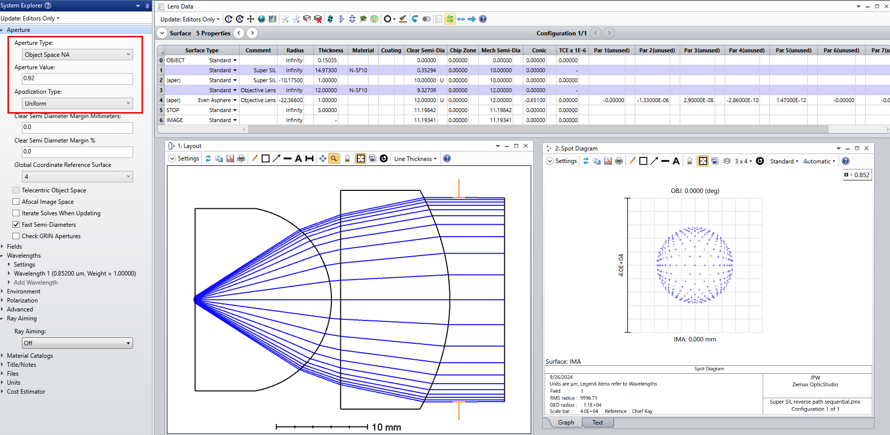
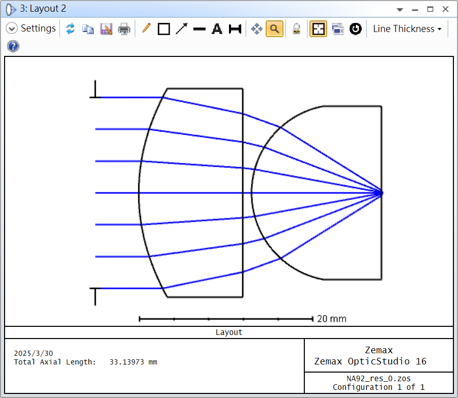
Since the geometry of the Weierstrass geometry is fixed, the only degrees of freedom that I have are the parameters related to my two aspherical surfaces. In the following figure you can take a look to the system I have at the moment:

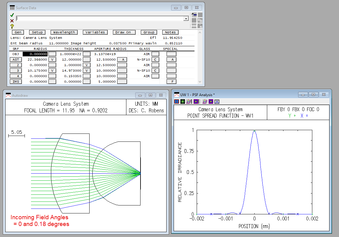
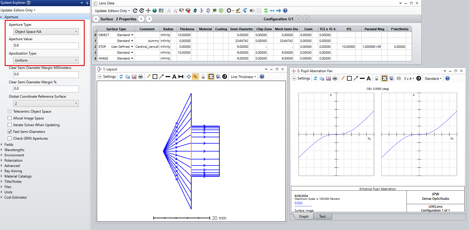
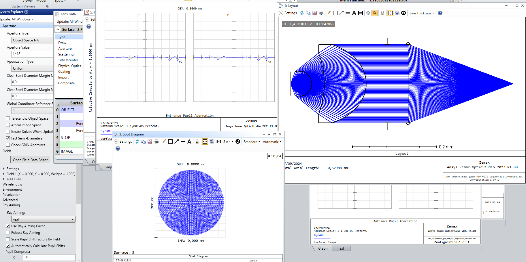
In this case, I optimized this system in the afocal configuration with the merit function defined to have a well corrected planar wavefront. After that I added the paraxial lens just to evaluat the PSF and to see how well corrected my system was.

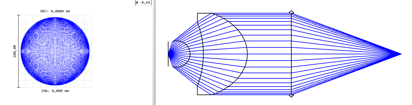
From the PSF evaluation I get a Strehl ratio of 1.0 and also from the wavefront map I get a well corrected performance.

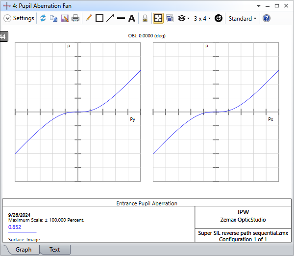
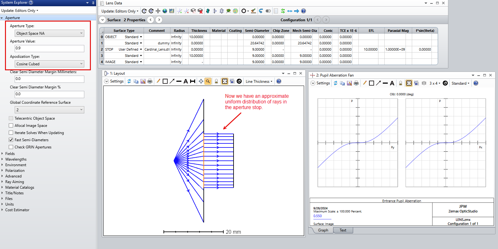
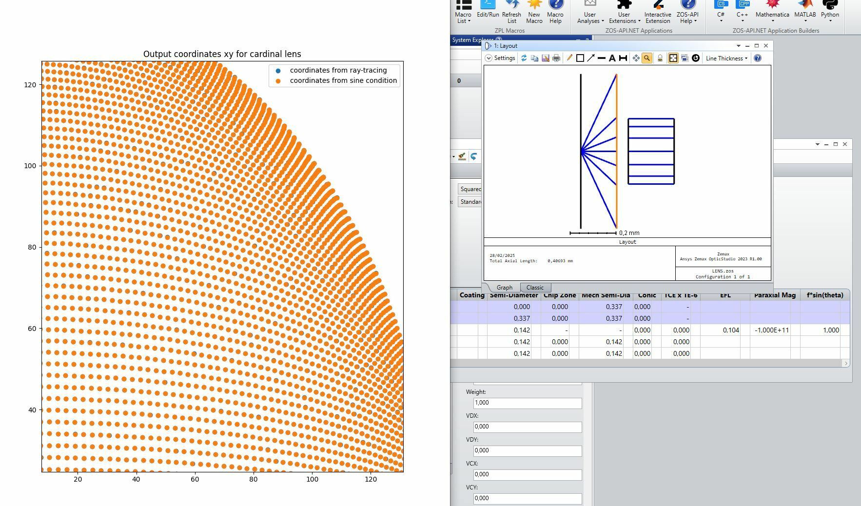
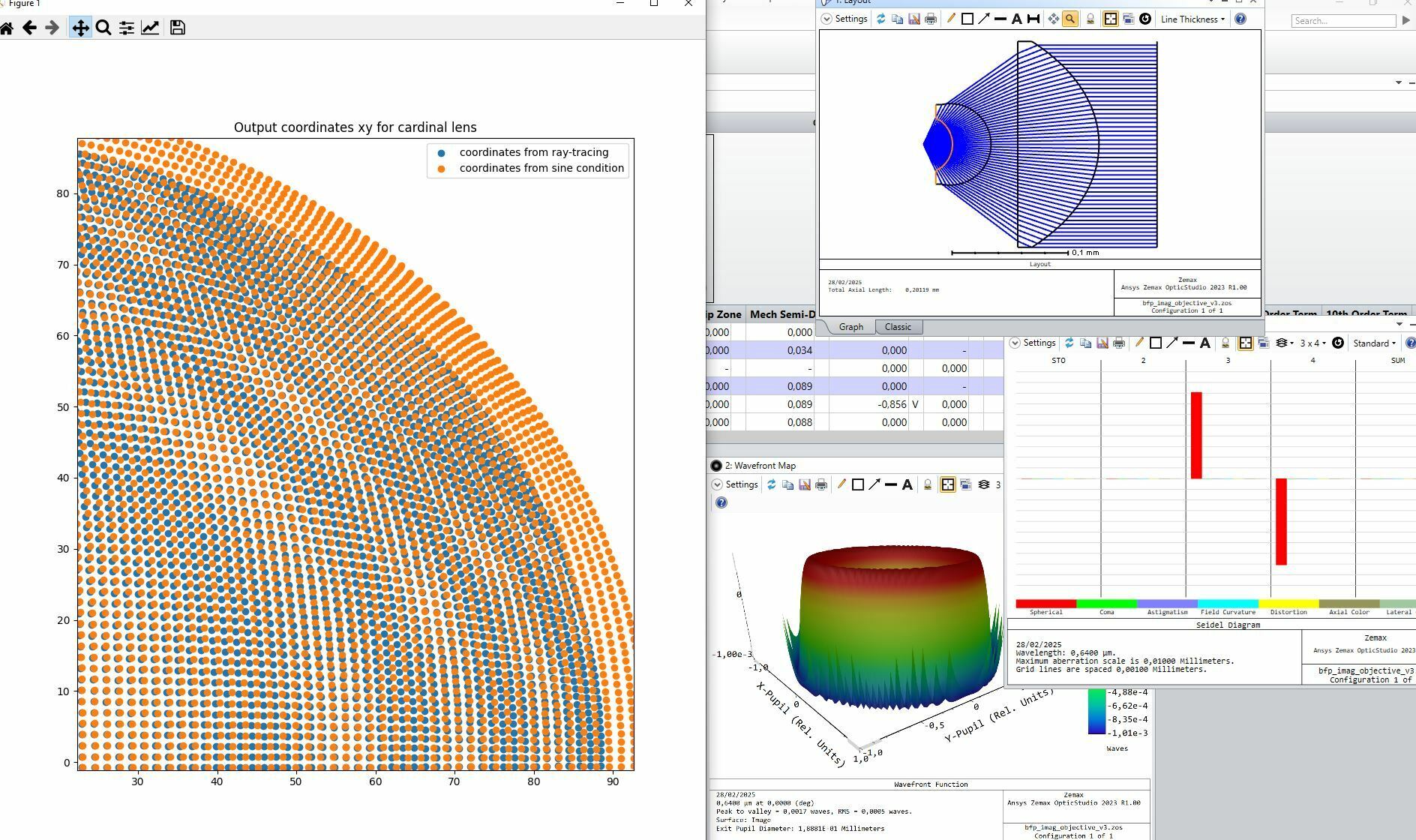
However, if you observe the ray density distribution right after the second aspherical surface and also from the spot diagram on the left side of the optical system, you can clearly see that the rays are not evenly distributed in the “collimated space”.

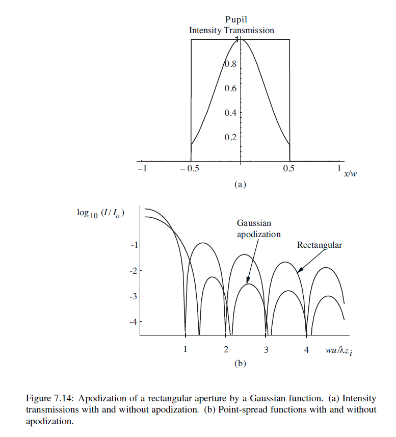
From what I know, if I had a uniform illumination right in front of the paraxial lens (given that the wavefront is well corrected) I would then get an ideal airy disk at the focal plane.

However, from such non-uniform ray density, I get an airy pattern that has stronger side lobes in contrast to the “ideal airy disk” case. 

Having said this, my question is then the following: If I wanted to generate an ideal imaging system, should I also care for the ray density distribution in the collimated set of rays? Is this something that is considered while doing these type of optical designs? If yes, how can I impose this condition into the optimization routine? 

All comments and feedback will be highly appreciated! 

@CJ27 

Try using cosine-cubed apodization,


That should help improve the uniformity in collimated space.  The PSF will change depending on the ray distribution because that, in turn, corresponds to a change in the exit pupil apodization.  For more detail, see Goodman’s book on Fourier Optics (Sec. 7.4.5, “Apodization and Its Effects on Frequency Response”).  Here’s an example of uniform vs Gaussian apodization:


Regards,

Jeff


I was giving a bit more thought to this problem and have some additional thoughts.  I took a look at the referenced paper, and it appears the “Weierstrass” solid immersion lens is better known in the optical data storage world as a “Super SIL” (versus a standard SIL that is a simple hemisphere). 

Using the layout details provided in the paper’s supplement, the non-uniform ray distribution in collimated space is indeed readily observed with the aperture stop placed at the objective lens and the aperture type chosen to be Object Space NA with Uniform apodization.

In this case, the paraxial entrance pupil is located about 33 mm away from the object plane and the source ray distribution is chosen to uniformly fill this pupil.  However, an actual point source radiating uniformly in angle space would produce a cosine-cubed power distribution on the flat entrance pupil plane.  Here’s a good article that mentions this detail:  What does the term apodization mean?

In this high-NA collimation system, there is significant pupil aberration:

which in turn means that even though the paraxial entrance pupil may have a uniform distribution of rays, by the time the rays reach the aperture stop the ray distribution is very non-uniform.  This is because there is not a simple linear mapping between the paraxial entrance pupil and the stop (recall the paraxial entrance pupil is simply a paraxial image of the aperture stop, but in reality there is substantial distortion present). This is to be expected and has nothing to due with conventional lens aberrations.  In fact, the same behavior can be found by using a “perfect thin lens” that obeys the sine condition (not a paraxial lens that is far from correct when used as a high-NA collimator).  Here is an example:


It is based on the Cardinal Lens user-defined surface, which models a perfect lens.  See the following link for more detail:


In any event, the problem is corrected by using cosine-cubed apodization:

In this case the rays do not have a perfect uniform distribution, but they are close to uniform.

However, another solution comes from keeping uniform apodization in place, but turning on real ray aiming.  So, in the Super SIL case it looks like this:

Now the ray distribution at the aperture stop in collimated space is truly uniform. 

Which approach is best?  I think the cosine-cubed version may be the more physically accurate choice for a real point source object like a fluorescing molecule, but ultimately I suppose it is up to the user to decide.

Sorry for the rambling explanation, but it’s actually a very interesting problem.

Regards,

Jeff


Hi @Jeff.Wilde,

Thanks a lot for the really nice reply and feedback. A lot of helpful information was given there 😀

In my original design (which is not the same as from the paper. The paper I use it as a reference for a high NA imaging objective based on the Weierstrass geometry) I had used an aperture of type “Object cone angle” with the aperture stop set directly at the Weierstrass surface.

After changing the aperture stop type to “Object space NA” and setting the STOP surface right after the second aspheric surface as you did, and finally using real ray aiming I can now see that I obtain a uniform distribution of rays in the collimated space:


Clearly, the pupil aberrations are significantly reduced after using ray aiming and the distribution of rays is also uniform as already mentioned.

In this case, I have not changed any parameter related to the design variables, i.e, I use the same coefficient values obtained from my original optimization which was done without ray-aiming and by using an object cone angle type of aperture.

From this, my question now is: In terms of optimization, what should I care for? Should I care for a uniform ray density in the collimated space and therefore consider the ray aiming option? Or would it be sufficient to just use my original approach without ray aiming and strong pupil aberrations? I dont notice any significant difference in terms of aberrations for the system. The only slight difference is in terms of the PSF, for which in the original case I get a PSF with more significant side lobes than when I have the uniform density (an “ideal” airy disk). I guess that using ray aiming and trying to get rid of the pupil aberrations is something that I would like to consider in general for such a high NA system right? 

Finally, I have tried using your perfect lens DLL model to replace the paraxial lens used to re-focus the collimated beam. However, I was not able to use it successfully. Would it be necessary for this scenario (focusing my colimated beam) to use the perfect lens model instead of the paraxial lens? 

Thanks a lot for the comments and feedback!


@CJ27

I think the way you originally optimized the lens system via afocal mode with wavefront error minimization is fine.  In that case I don’t think it matters whether or not you have ray aiming turned on because the OPD calculation is done over the entire pupil based on the user-supplied sampling -- as long as the sampling is sufficient, the OPD function should be independent of the ray apodization (or the ray uniformity in collimated space). 

However, I would not suggest optimizing with the paraxial lens in place unless it is operating at f/4 or slower.  As noted in the help documentation, the OPD calculation for a paraxial lens is prone to error if the f/# is too low.


If you did want to include a perfect thin lens at low f/#, here are examples of doing that with the Cardinal Lens.  The Cardinal Lens, if used properly, will compute the correct OPD for low f-numbers.  Information on how to use the Cardinal Lens is provided in Section 4 of this paper Ray-tracing model of a perfect lens.  It works a little differently than a paraxial lens surface; one main difference is that the thickness parameter of the Cardinal Lens surface corresponds to the separation between the principal planes of the lens (i.e., the Cardinal Lens can mimic an ideal thick lens, but if the surface thickness is set to zero then it’s an ideal thin lens).

Case 1 (uniform apodization with real ray aiming)


Case 2 (cosine-cubed apodization without ray aiming)


In both cases you see the OPD fans (wavefront error functions) are quite similar, with the differences being well below the diffraction limit. 

Lastly, I’ll mention that lens design is often done in the reverse direction, going from collimated object space to focused image space.  That’s how the authors of the paper did their design (in  OSLO):


In this case, you don’t have to worry about ray aiming because the entrance pupil (EP) corresponds to the aperture stop (AS).  So uniform apodization will obviously fill both the EP and the AS uniformly.  You would most likely want to change the aperture type to Entrance Pupil Diameter and make sure your field points are defined in terms of angles. 

Regards,

Jeff


Reply