Question

Focal position shift with beam divergence (NSC).

  • February 4, 2025
  • 4 replies
  • 100 views

pricecj

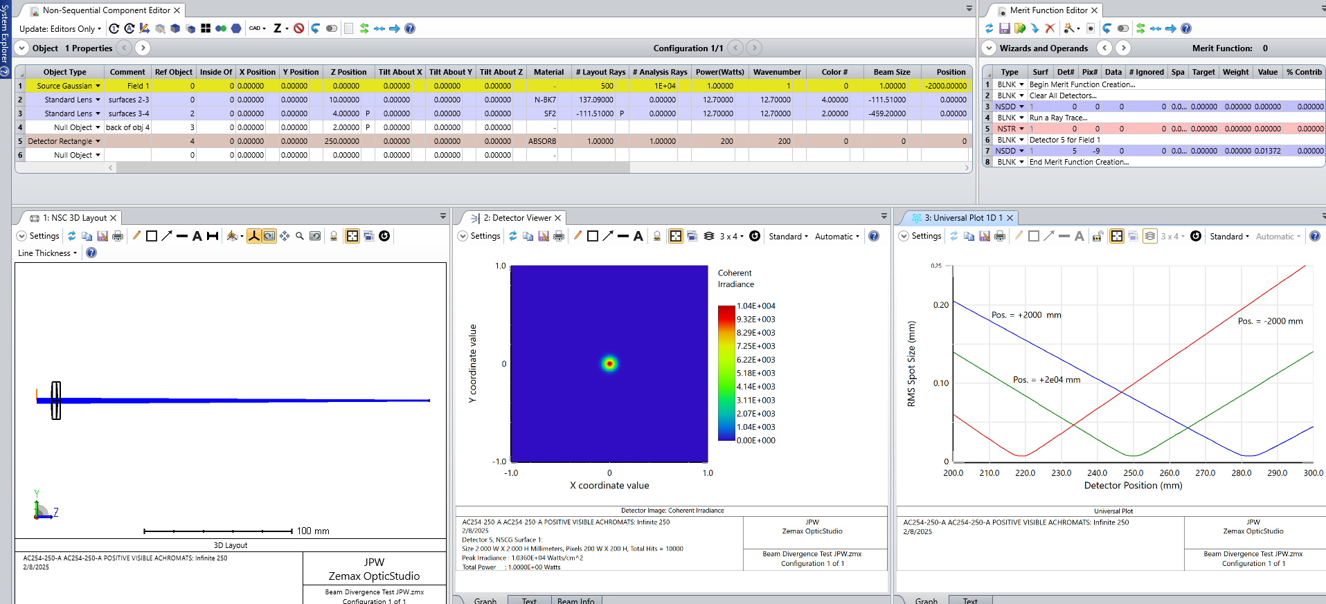
I have setup a simple experiment in non-sequential mode to test the effect of beam divergence on focal position. The lens file I am using is from the Thorlabs website (f=250 mm, VIS achromat). I set the divergence value (or collimation) using a Gaussian Source with the appropriate beam size and position (P) values, and then scan a detector rectangle along the optical axis measuring the beam waist a various locations. Contrary to my knowledge of  geometric optics, the focal position shifts closer to the focusing lens with increasing beam divergence; I am using divergence angles of 0.04-0.08 mrads (half angle). Interestingly, when I set the Position value to give a converging beam, the focal position shifts away from the focusing lens. I’m concerned that there is something that I have missed when constructing this model, and was wondering if anyone could help? I have uploaded my Zemax file for convenience. Many thanks, Chris. 

4 replies

Jeff.Wilde
Luminary
Forum|alt.badge.img+3
  • Luminary
  • 490 replies
  • February 5, 2025

Your attachment only has the ZDA file.  You should also include the ZMX model file.


pricecj
  • Author
  • Monochrome
  • 4 replies
  • February 7, 2025

Hello Jeff,

Thanks for your email. Please find attached the correct files.

Many thanks

Chris


Jeff.Wilde
Luminary
Forum|alt.badge.img+3
  • Luminary
  • 490 replies
  • February 9, 2025

Hi Chris,

I took a look at your file, and I don’t see any problems.  Here is a slightly modified version:


In the bottom right window, the RMS spot size vs detector position is plotted for three different Gaussian point source locations (i.e., “Positions”).  For a position of +2e04 mm, which is much larger than the lens focal length, the focus occurs near the back focal plane.  However, if the position is reduced to +2e03 mm (which means the point source moves closer to the lens and the divergence angle of the rays at the location of your source plane increases), then the image point moves farther away from the back focal plane as expected.  Similarly, for a position of -2e03 mm, the image point moves closer to the lens.  So all appears to be okay. 

Here are few additional comments.  First, you had the detector operating in PSF mode, which is fine but not really necessary.  In fact, doing so causes a dramatic slow down because of the increase in computational load.  Second, if all you are interested in doing is modeling a Gaussian beam through a lens, sequential mode is probably a better option.  In that case you can apply Gaussian apodization to the beam, set the size of the beam at the lens by locating the stop there, and then use quick focus to find the image point.  You can also use the geometric or PSF spot size tools, or employ Gaussian beam analysis and/or physical optics propagation to more fully account for the Gaussian nature of the beam (i.e., account for diffraction during propagation). 

Regards,

Jeff


pricecj
  • Author
  • Monochrome
  • 4 replies
  • February 10, 2025

Hi Jeff.

Many thanks for your response. This information is fantastic, and I will use your suggestions going forward. However, I’m still a little puzzled with the results I am seeing using my approach. Let me give you some context. My aim is to calculate the divergence of a (source) laser beam using the method described in ISO 11146-1. This involves passing the source beam through a lens and measuring the beam profile before, at, and after it focuses; a hyperbolic fit of the beam size as a function of axial position will give 3 parameters that can be using to calculate the divergence of the source beam (before the lens). I wanted to create a model were I could use a known beam divergence value, and use the results to verify my calculation using the ISO method. As mentioned previously, I scanned the detector position along the optical axis measuring the beam size at several points (1/e2 diameter), I do this manually using a Gaussian fitting routine to the beam profile data. I then plot beam size as a function of optical axis position (manually) and look for the position of the point of inflection i.e the location of the smallest beam size. This is where I am seeing the issue of the smallest beam size begin shifted closer to the focusing lens with an diverging beam source, and moving away from the lens with a converging beam source. I was expecting to the see the result as you have shown with your analysis, but this is not the case. The reason I set the model up in this way is so that I could directly assess the beam size at various points along the optical axis, taking diffraction into account if necessary.


If I can extract this data from your proposed method, then great, but I was just curious as to why my initial approach is giving incorrect/misleading results.


Many thanks for your time

Chris


Cookie policy

We use cookies to enhance and personalize your experience. If you accept you agree to our full cookie policy. Learn more about our cookies.

 
Cookie settings