Question

Fixed apertures in Image simulation


mocquin
Ultraviolet

The documentation about Image Simulation on the “Apply fixed apertures” is : 

Apply Fixed Apertures If checked, all surfaces with optical power that have no aperture defined are modified for this computation to have a circular aperture at the current clear semi-diameter or semi-diameter value. Without this change in the aperture definition, rays may pass the surface beyond the listed clear semi-diameter or semi-diameter, especially if the Field Height exceeds the field of view defined by the field points. This leads to misleading illumination, typically at the edges of the image.


I’m kinda confused by the vocabulary here, probably just by lack of knowledge on my side.

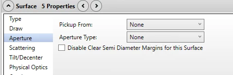
In the first sentence, “… have no aperture defined...” refers to the surface’s Aperture data ? so that means “for surfaces whose Aperture data is None for Pickup From and Aperture Type” ? - like so : 


Then, “to have a circular aperture at the current clear semi-diameter” : from what I understnd, with “Clear Semi-Diameter” solve as Automatic, the value of a surface’ clear semi-diameter is computed at the appropriate height so that it does not vignette any ray. so I don’t understand how or why a ray in the image simalution would go beyoud this height.

To go a bit further, I am actually trying to understand how this works because I’m getting very deep black spots in the corner of my image based on Apply Fixed Aperture being checked or not, and I don’t understand where it comes from (I disabled Polarization and Relative Illumiatnion, so it really comes from Fixed apertures)

Checked : 


Unchecked : 


Another thing I don’t understand is how this vignetting by diameters differs from what is included in the relative illumination, which is pretty flat and does not have such drops at diagonal height

2 replies

MichaelH
Ansys Staff
Forum|alt.badge.img+2
  • Ansys Staff
  • 381 replies
  • July 15, 2025

Hi ​@mocquin,

This statement in the Image Simulation basically means that if you don’t have fixed apertures applied and if you set the Field Height and Field to a value where the Input File is larger than the Field of View in the FDE, then the Clear Semi Diameters in the LDE will automatically increase to trace the PSF at the larger FOV.  In almost all systems, this is unrealistic since the diameter of the lens doesn’t increase depending on which part of the FOV you’re analyzing.  

Since Image Simulation is typically a final analysis once a design is mature and stabilized, I’d suggest running the Tolerance > Design Lockdown tool before running the Image Simulation (you can always reverse the Design Lockdown if you have Undo enabled).  The Design Lockdown turns a sequential system with non-physical attributes (like defining the aperture as Entrance Pupil Diameter rather than the physical size of the Stop or applying fixed apertures to all optical surfaces) into a physically realistic system.  This tool is intended for tolerancing where you need to have a physically realistic system, but it is also useful for things like comparing a sequential model to a non-sequential model or running Image Simulation.

My guess as to why you’re not seeing the drop-off in the Relative Illumination plot is this is only tracing rays in the +y direction, not in the diagonal direction.  For example, if your system is design for a maximum Object Height of 10mm and you have a square input file of 10mm Object Height, then the edge of the output file will actually be at 14.1mm (beyond the intended FOV); you will need to apply hard apertures to the system to accurate represent the vignetting at this increased FOV.  If you calculated the diagonal of the Input File and then increased your Field Data Editor to this value, you should see a similar RI roll-off.


mocquin
Ultraviolet
  • Author
  • Ultraviolet
  • 38 replies
  • July 16, 2025

Oh, I think I see it now…

I’ll rephrase it to make sure I get this right, let me know if something is wrong or misleading  : So if “Apply Fixed apertures” is checked, then, just for the time running the image simulation, fixed circular apertures are applied to surfaces at their current clear diameters - in that way, rays coming from outside the field of view will be vignetted. 

Otherwise, if Apply Fixed apertures is not checked, the current clear diameter are extended in order to accept all object angles specified by the source height, just like adding a big new field in the field editor would make the diameters bigger to accept it.

Another way to explain this mistunderstanding is that I’d expect the LDE content not to change when running an analysis, while from what I understand, the Object Height of the Image simulation works similarly to creating new fields, and so new clear semi-diameters.

Now regarding the relative illumination, I already have a Y-field at the image diagonal height so the RI goes from 0 mm height to the image diagonal height. In the image simulation, the image input has the same resolution as the intended FPA, and I set the object height equal to the FPA vertical size. Is there a way to introspect ray propagation that are used to compute the image simulation ?


Reply


Cookie policy

We use cookies to enhance and personalize your experience. If you accept you agree to our full cookie policy. Learn more about our cookies.

 
Cookie settings