Dear OpticStudio users,
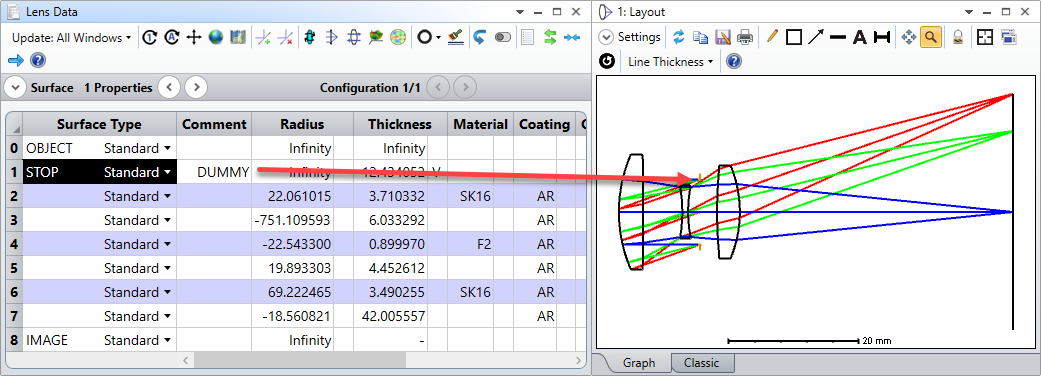
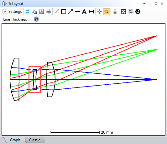
I had to replicate the design of a patented lens (US patent US7199938) in the context of my research at the MRC - Laboratory of Molecular Biology. In this patent, all surfaces are thoroughly described (radius, thickness, refractive index, and Abbe number), but it is never specified were the STOP position is. It is the second time I am facing this issue, and here is how I went about it:
- I have reversed the objective lens to have the specimen plane as the IMAGE plane. I am doing so because, usually, the aperture is at the back of the objective lens, and I can avoid using ray aiming (in the end I don't think it makes a big difference, and its probably fine to work with the forward model).
- I have created 5 equal area Y fields (only along Y because it is a rotationally symmetric design) that fill the field number of the objective lens.
- After the OBJECT surface (Surface 1), which has an infinite thickness in the reversed state, I have put a dummy surface (Surface 2) with a variable thickness.
- After the dummy surface, I have put the STOP surface (Surface 3), and its thickness is a pick-up of the dummy surface (Surface 2) with a -1 scale factor.
- I have created a default Merit Function to optimize for the spot size,and ran the automatic local optimizer.
This virtually placed the STOP surface where it gave sensible results (based on a comparison with a matrix optics approach). I didn't have to place thickness constraints on the variable thickness, but it can be done if necessary, I guess.
What do you think about this method? Can you see any downfalls? What other reverse engineering tricks do you use to get this kind of information?
I happy to make a more pedagogic post if there is an interest in this topic.
Kind regards,
David