FIber coupling FICL operand

  • 9 November 2021
  • 10 replies
  • 971 views

The FICL operand is used for beam - fiber coupling optimization. 

But the FICL for optimization used only NA  (numerical apertures) of fibers.

Does the fiber mode field diameter (MFD) makes any impart on coupling efficiency ?

The MFD very important in coupling but in optimization with FICL its looks like the fibers MFDs doesnt used.

How to include the fiber MFD in optimization with FICL ?


10 replies

Userlevel 6
Badge +4

Hello Arkadiy,

For a single mode fiber, the MFD and NA are not independent. If they are both measured at the 1/e^2 point of the Gaussian profile, then MFD = 2 lambda/(Pi NA). So we can only specify one.

Thanks David, that is really usefull

One more question:

If the fiber have a tilted face (like APC/PC connector tip) the FICL operand canbe used to optimize the fiber-beam coupling ?

In FICL settings is X Angle (deg), Y Angle (deg) for source fiber and Tilt About X (deg), Tilt About Y (deg)  for reciever fiber. Thet settings defines the fiber rotation itself not fiber tip tilt.

How to take into account the fiber tip tilt by FICL means? Is it possible ?


Userlevel 6
Badge +4

I can thing of one way that seems to make sense. I started with the file attached to the knowledge article Single-mode fiber coupling in OpticStudio by Mark Nicholson and Kristen Norton. The file was the one for after optimization by FICL.

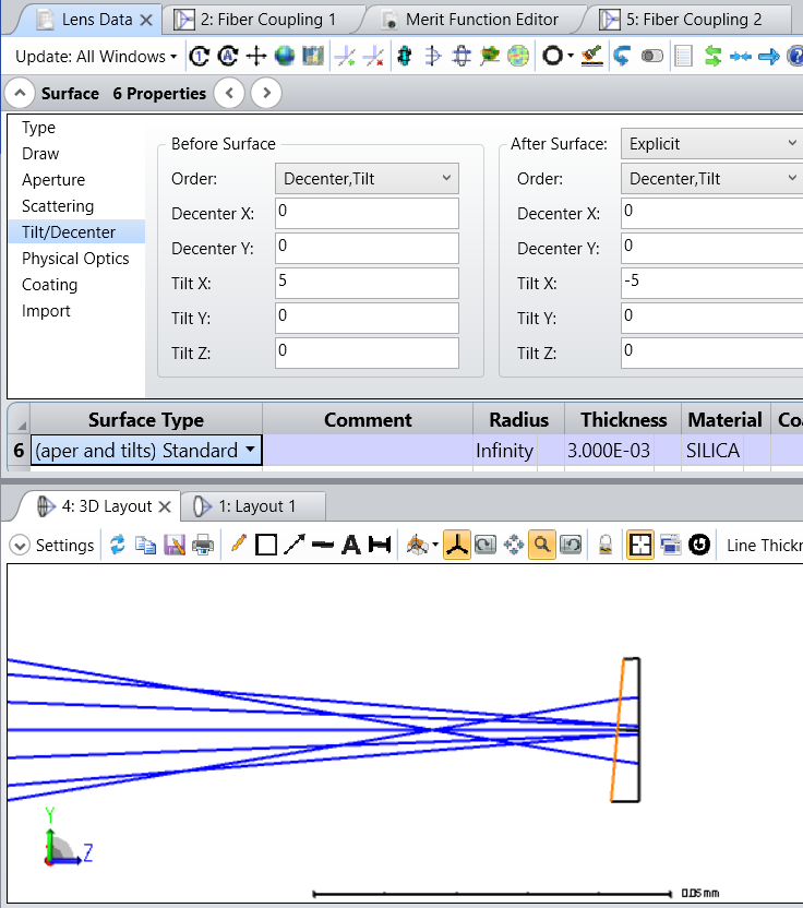
I added a very thin silica window before the image plane. In the FICL analysis polarization is not checked nor is align fiber to chief ray. So the wave front of the irradiance on the fiber should be deflected by the refraction and the fiber will not be tilted to follow it.

Window with tilted face

With no tilt on the window face and the system reoptimized fiber coupling reports:

     System Efficiency               :           0.999164

     Receiver Efficiency             :           0.990401

     Coupling Efficiency             :           0.989573     (-0.0455 dB)
 

With 5 degree tilt on the window face and the system reoptimized fiber coupling reports:

     System Efficiency               :           0.999164

     Receiver Efficiency             :           0.825313

     Coupling Efficiency             :           0.824623     (-0.8374 dB)


So it appears that the tilted face has reduced the mode overlap integral.


If we’re lucky. @Mark.Nicholson will comment on this and we’ll both learn something. ;-)


Userlevel 7
Badge +3

Well, I presume the wedge shifts the beam so it no longer overlaps perfectly. Isn’t this what you’d expect?

Userlevel 7
Badge +3

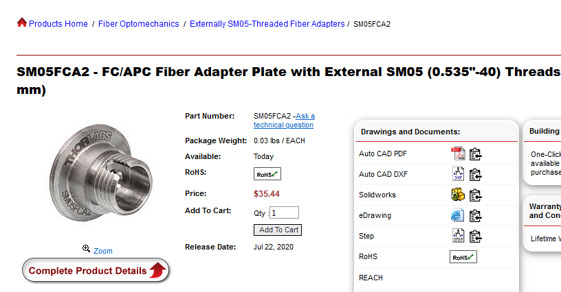
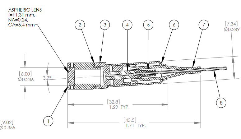
My experience is that for purposes of optimizing the coupling optics, the endface tilt of an APC-connectorized fiber can be neglected because in practice the fiber will typically be mounted with the appropriate tilt relative to the optical axis.  For example, see Thorlabs part SM05FCA2 (SM05FCA2 - FC/APC Fiber Adapter Plate):


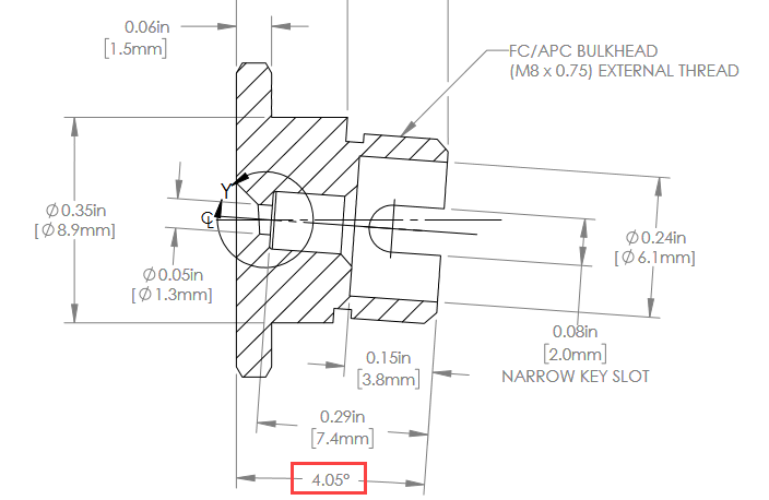
Here is a screenshot from the AutoCAD PDF drawing showing the detail.


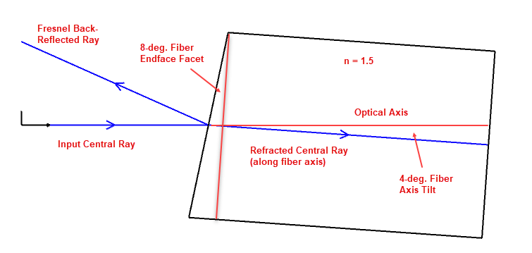
In other words, from the viewpoint of the coupling optics, a non-angled fiber (FC/PC) mounted with the fiber axis parallel to the optical axis is essentially equivalent to an endface-angled fiber (FC/APC) mounted at a 4.05-deg. angle to the optical axis.


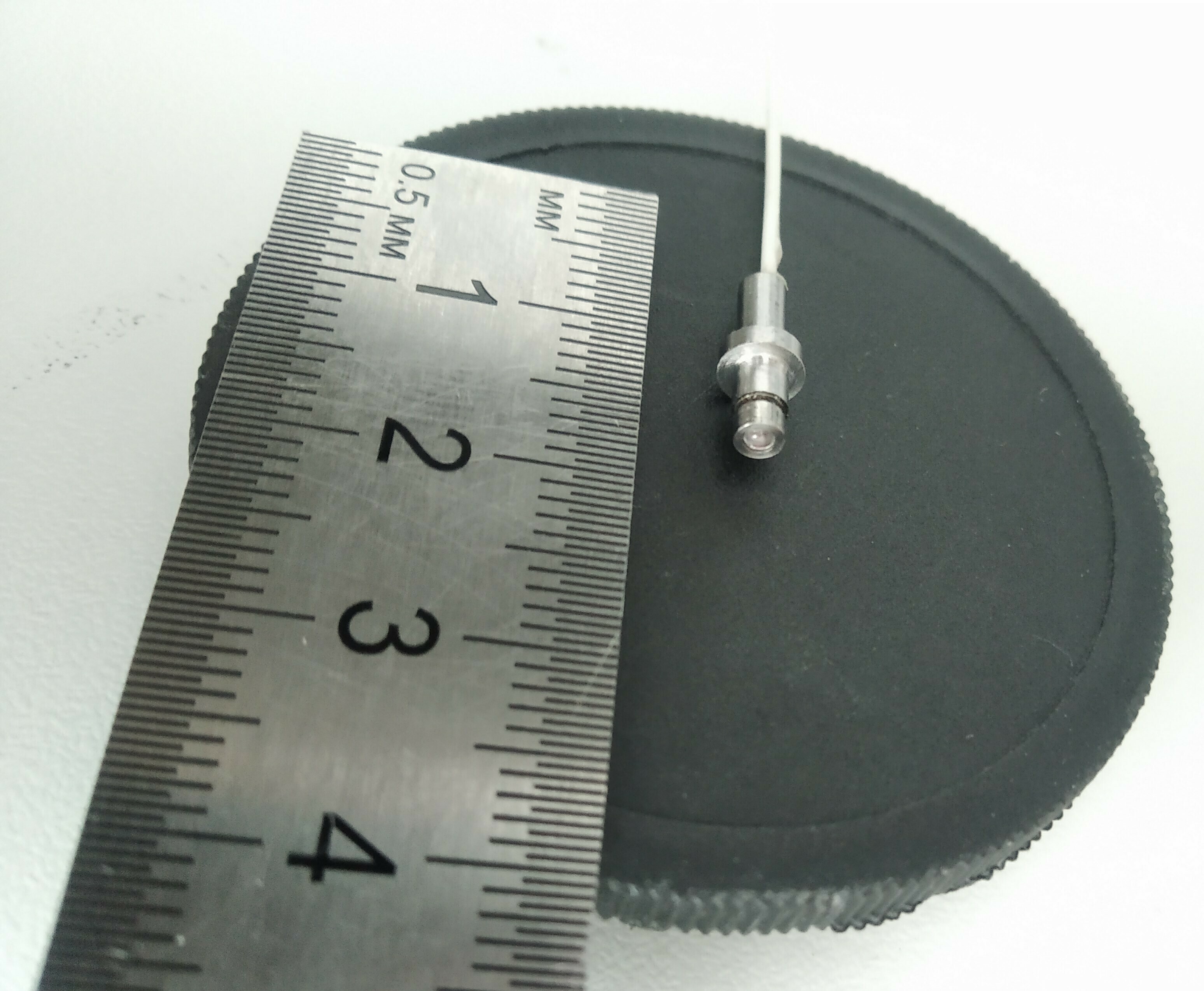
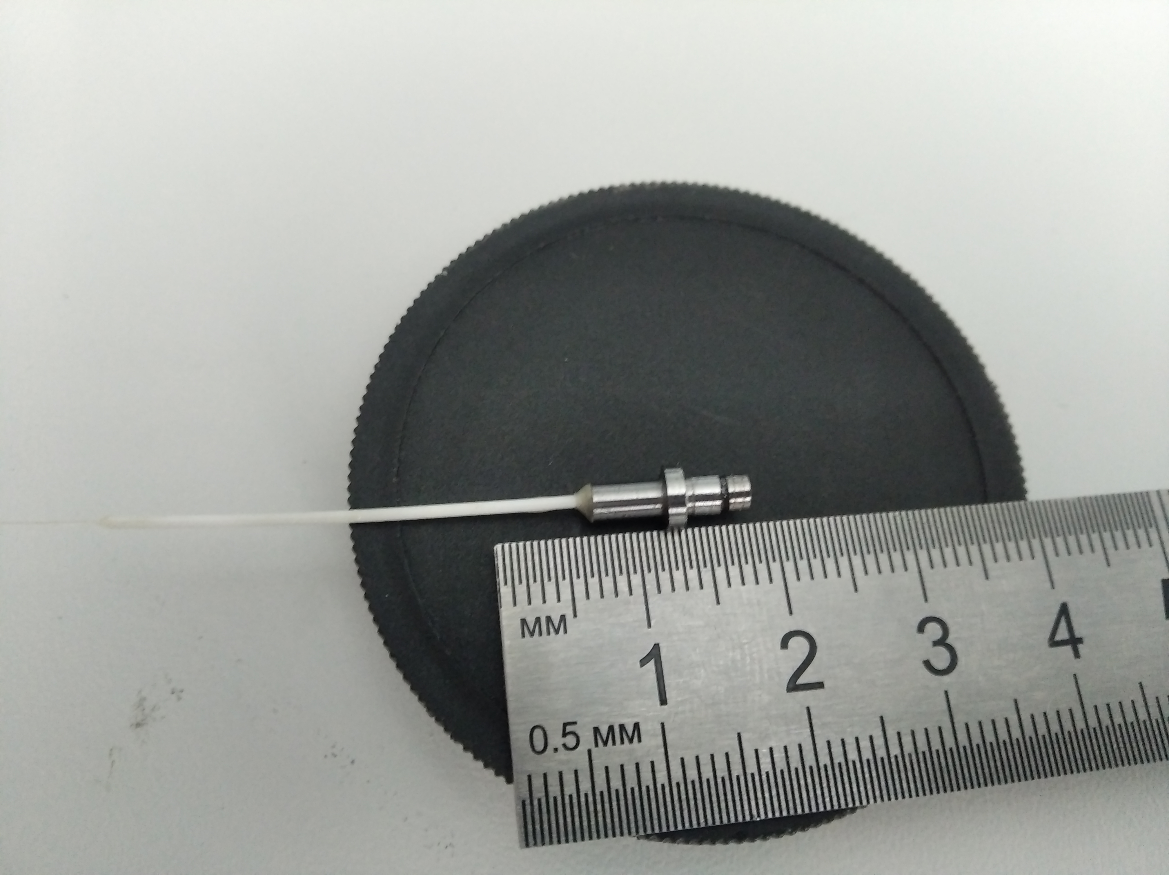
I try to make that collimating package. It have tilted 4 deg fiber face and 1.5 mm diameter ball lense. The fiber is SMF 28. The ball is installed into the tube and tube is welded by laser with part that encloses fiber.


The purpose is to make expanded beam collimating pair.

So I try to find the ball position with relative to fiber to get accepting efficiency of pair.

With production technology I have now I can’t  tilt the collimator fiber body like Thorlabs example.

Now I glued a 1.25 ferrule with fiber into cylinder body. After in a grinding machine I make the fiber in center of collimator body. So my fiber is disposed in center of collimating body. Later the ball tube is welded.

Thats technology. 

I think I have to develop a method to tilt the collimator body like Thorlabs.


Userlevel 7
Badge +3

Yes, if you need to use a standard angled-fiber (8-deg. facet), then I think you need to mount it with a 4-deg. tilt (or a tilt value close to 4 degrees depending on the index of the fiber your operating wavelength).


Thorlabs also sells FC/APC collimator packages that use this approach (for example, see CFS11-1550-APC - SM Pigtailed Aspheric Collimator)


A ball lens will be much less expensive than a molded asphere, but the coupling efficiency will be somewhat lower.  OpticStudio can tell you the answer.  Good luck.


Reply