Solved

Fiber Coupling

  • 8 September 2020
  • 9 replies
  • 646 views

Hello All,


I am trying to couple the 50-watt laser diode to multimode fiber. But the given diode is 10 watt. Therefore  5 diodes (each of 10 watts) are needed to achieve the 50-watt power.  Can we simulate this system using sequential mode?


Thank you

icon

Best answer by Angel Morales 29 September 2020, 18:39

View original

9 replies

Userlevel 5
Badge +1

Hi Neha,


In Sequential Mode, the power of any field point you define isn't really specified directly, as the power between field points is defined as a relative value.


For evaluating multi-mode coupling in Sequential Mode, though, you can use something like the Geometric Image Analysis tool -- the article here explains in more detail how the tool works. In short, you can specify the input power of your source (which you can adjust to 50 Watts) and specify the NA required at the Image plane for coupling:


This would be the most straightfoward way to set up the model. Otherwise, you could attempt to construct a custom input beam profile to use in POP that mimics the 5 diode array you'd like to set up. For example, you could use the Multimode setting in POP to generate an input beam profile of a few discretely-placed Gaussian modes -- though, of course, this does assume that your system will be compatible with POP computations (from our Help Files at 'The Analyze Tab (sequential ui mode) > Laser and Fibers Group > About Physical Optics Propagation > Defining the Initial Beam > Multimode'):


I think these would be the most straightforward approaches to modeling the multi-mode system you've described, as a lot of our Sequential Mode analyses are dependent on obtaining results for a specific field point. So, if needed, you could also run Geometric Image Analysis to obtain the coupling efficiency at different field points (each modeling a different LED source), but you wouldn't be able to have one GIA window reporting all that data.


Please let us know how these thoughts work out for you! Thanks again for your discussion here.


~ Angel

Hello Angel,


Thank you for your response. The thing is I have to use a single  10 watts diode. And the obtaining output should be 50 watts. So, to construct the 50 watts FCLD, I think I have to use 5 or 6  (10 watts ) diodes.


In this case, we have to use a spatial beam combination and polarization beam combination methods to enhance power. 


can we use these methods in the sequential mode of Zemax?


Please also suggests to me how we can design an array of diodes.

Userlevel 5
Badge +1

Hi again Neha,


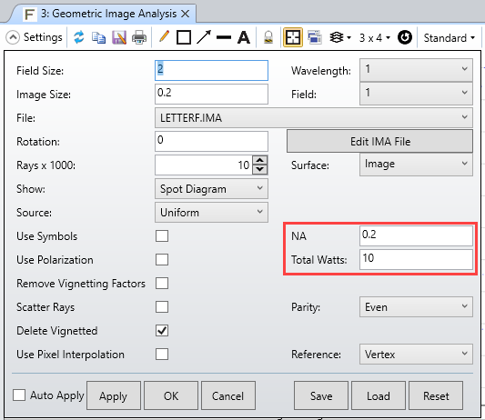
If you wanted to stay in Sequential Mode, I think you would need to use something like Geometric Image Analysis and modify the spacing of the field points to simulate 'optimizing' the spacing/arranging of the diodes. That said, I think the most intuitive and straightforward way to perform this optimization may actually be using Non-Sequential Mode. I say this because you'll have direct control over the near- and far-field distribution of your sources (depending on the Source Objects you select), and you will have much more control of where they can be placed. In Sequential Mode, if we define different field points, one of the main assumptions is that each field point will have a distinct landing coordinate for things like the chief ray on the image plane, particularly if this is meant to be a 'focusing' system.


So, if you use different field points to simulate multiple diodes, but then attempt to focus them all at the same point on the image plane, I think OpticStudio will have some difficulty in performing some of its computations. This would not be an issue in Non-Sequential Mode, though, since the ray trace does not make the same assumptions.


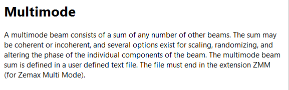
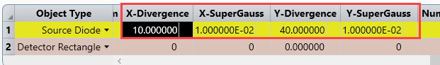
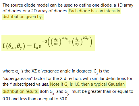
For more information on defining an array of sources in NSC Mode, you can take a look at this Knowledgebase article here. Though it details the setup, once the array has been created, you can place Detector objects where you'd like within your system to monitor your desired performance metrics.


Please let us know if you have any more questions here!


~ Angel

Thank you, Angel,


It helps me a lot. Here, I fixed the power 10 watts of single emitter. Now for the formation of multi-emitter diodes, where we will fix the values of the y-axis divergence (40 degrees) angle and X-axis divergence angle (10 degrees) of the single emitter?


Because for better coupling efficiency, we have to minimize the divergence angles values.


Please see the attached file. 

Userlevel 6
Badge +2

Hi Neha


Have a look at those two models of sources:


- Source Diode


- Source Two Angle


Sandrine

Hello Sandrine,


Thank you for your response, Non sequential mode is new for me. 


Please see the attached file, here I am trying to build a 50-watt laser diode from 6 single emitters in a 3*2 array. I set the x divergence is 10 deg and y divergence is 40 deg. Because my single emitter specification is like this


fast axis divergence angle  = 40deg


slow axis divergence angle  = 10deg


power = 10 watt


But my result is no accurate. it seems inaccurate. Is there a spacing problem between X and Y (delta X and delta Y) or something else which is not accurate? Please let me know. 


My question is where we will use the fast axis and slow axis collimator?


How we can minimize the divergence angle?

Userlevel 5
Badge +1

Hi Neha!


When you mention 'divergence angle,' is this a measurement of the angle to the 1/e^2 point? Full width at half maximum? Depending on your specifications, it will affect how the Source Diode object should be modeled.


The Source Diode object is meant to be able to model a wide range of diode emitters, and as a result, there are a lot of settings to consider in its definition. For one, when you define the angular distribution, you will be looking at the X/Y Divergence and X/Y Supergaussian settings:


In our Help Files at 'The Setup Tab > Editors Group (Setup Tab) > Non-sequential Component Editor > Non-sequential Sources > Source Diode,' we have some information on how these parameters affect the distribution of emitted rays in angle space:


So, if the divergence angle is meant to be the 1/e^2 point, then you'll want to define a Gaussian distribution by setting the X/Y Supergaussian factor to 1. The Help Files at that page also note a helpful method for converting your parameters to a FWHM spec, if that's what you're working with:


As for optimizing the system and placing your optics in the model, I think you can take a look at the following article here. The example covered isn't exactly the same as your system, but it does cover the non-sequential optimization, including obtaining peak power with minimal divergence angle. You can also take a look at the following articles for more resources on the Optimization Wizard settings in NSC mode, as well as a general overview on this mode of OpticStudio:


~ Angel

Hello Angel,


Yes, i am taking 1/e^2 into consideration and changed the X/Y Supergaussian factor to 1 . Now, how we get the efficient coupling between diode array and multimode fiber. How we can reduced the values of fast axis and slow axis divergence? 


Userlevel 3
Badge +2

Hi Neha, 


If you want to calculate the coupling efficiency in Non-Sequential you can just record the power entering the fiber and the power out of the fiber, and the efficiency will be the power fraction. There is an example in the folder Samples/Non-Sequential/Fibers/Fiber with tilted face.


To minimize divergence, you may target the 'RMS Angular radius' as explained in this article:


https://my.zemax.com/en-US/Knowledge-Base/kb-article/?ka=KA-01591


Best,


Berta

Reply